Method, apparatus, and system for mounting an electronic device utilizing a battery cover

Inactive Publication Date: 2009-04-23
GARMIN
View PDF5 Cites 9 Cited by
  • Summary
  • Abstract
  • Description
  • Claims
  • Application Information

AI Technical Summary

Benefits of technology

[0006]In various embodiments, the present invention provides a battery cover for an electronic device including a battery receptacle. The battery cover generally comprises a base and a cover mating element. The base is operable to couple with a portion of the electronic device and at least partially cover the battery receptacle. The cover mating element is operable to couple with the base and interchangeably mate with a reciprocal mating element associated with a mount to couple the electronic device to the mount. In some embodiments, the cover mating element may be operable to interchangeably mate with a plurality of reciprocal mating elements associated with a plurality of mounts to enable the electronic device to be coupled to any one of the mounts.

Problems solved by technology

For example, an electronic device configured for mounting using a ball and socket configuration may be unable to mount with mounting devices that employ other configurations.
Thus, users are often unable to employ electronic devices in a plurality of mounting configurations.

Method used


Image

  • Method, apparatus, and system for mounting an electronic device utilizing a battery cover
  • Method, apparatus, and system for mounting an electronic device utilizing a battery cover
  • Method, apparatus, and system for mounting an electronic device utilizing a battery cover

Examples


Embodiment Construction

[0024]The following detailed description of various embodiments of the invention references the accompanying drawings which illustrate specific embodiments in which the invention can be practiced. The embodiments are intended to describe aspects of the invention in sufficient detail to enable those skilled in the art to practice the invention. Other embodiments can be utilized and changes can be made without departing from the scope of the present invention. The following detailed description is, therefore, not to be taken in a limiting sense. The scope of the present invention is defined only by the appended claims, along with the full scope of equivalents to which such claims are entitled.

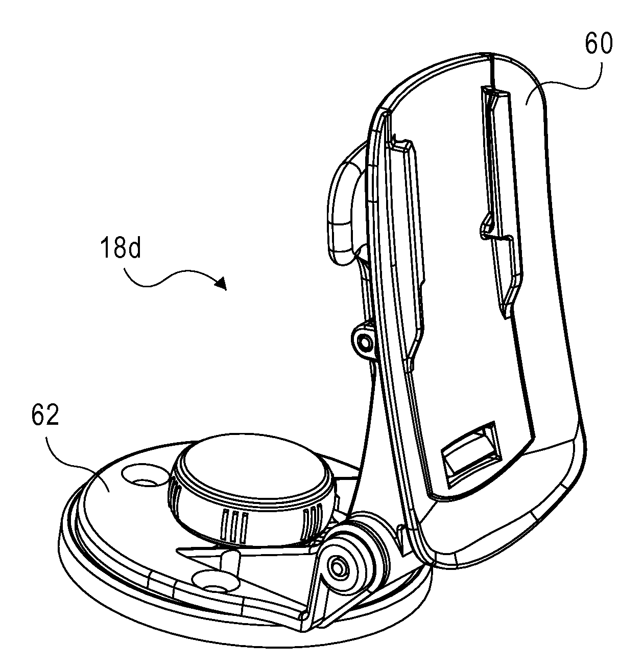
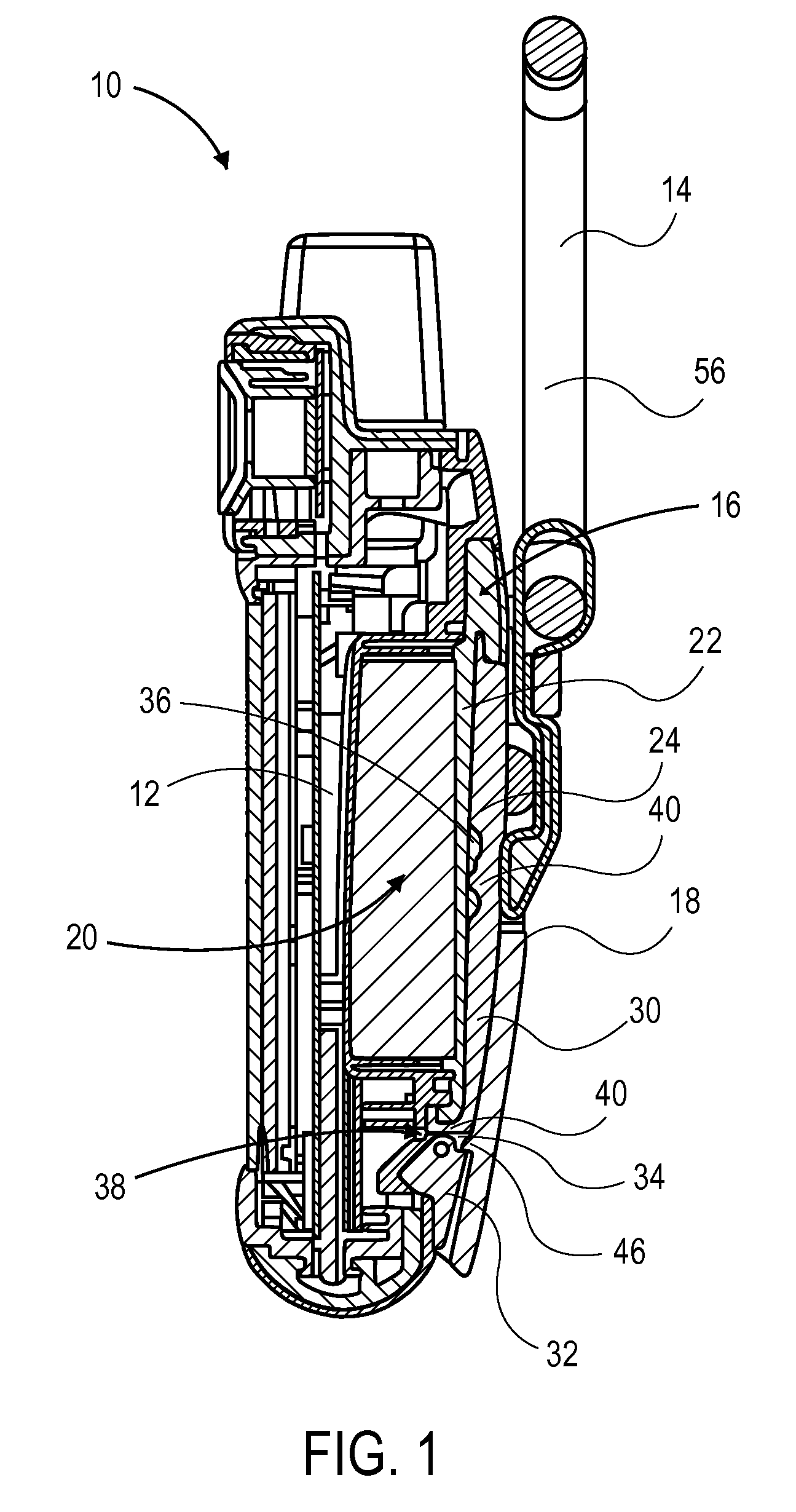
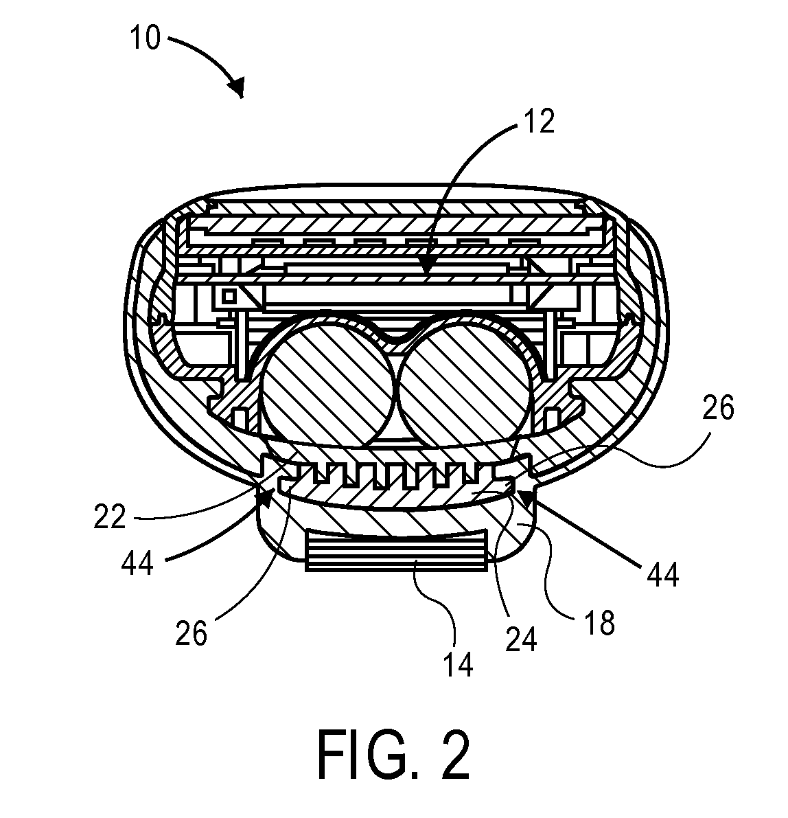
[0025]Various embodiments of the present invention provide a mounting system 10 for securing an electronic device 12 to one or more mounts 14. As illustrated in FIGS. 1 through 14, the mounting system 10 may broadly include a battery cover 16 and one or more reciprocal mating elements 18. The bat...


PUM


Abstract

A battery cover for an electronic device including a battery receptacle. The battery cover generally comprises a base and a cover mating element. The base is operable to couple with a portion of the electronic device and at least partially cover the battery receptacle. The cover mating element is operable to couple with the base and interchangeably mate with a reciprocal mating element associated with a mount to couple the electronic device to the mount.

Description

BACKGROUND[0001]1. Field[0002]Embodiments of the present invention relate to the mounting of electronic devices. More particularly, various embodiments of the invention provide methods, apparatuses, and systems for mounting an electronic device utilizing a battery cover associated with the electronic device.[0003]2. Description of the Related Art[0004]Electronic devices, such as personal navigation devices, may be mounted in various environments including automobile, motorcycle, or bicycle environments to facilitate their use and enjoyment. Electronic devices often are configured for mounting utilizing only one mounting configuration. For example, an electronic device configured for mounting using a ball and socket configuration may be unable to mount with mounting devices that employ other configurations. Thus, users are often unable to employ electronic devices in a plurality of mounting configurations.SUMMARY[0005]Embodiments of the present invention provide a distinct advance in...

Claims


Application Information

Patent Timeline
IPC IPC(8): F16L3/00B23P11/00H01M2/08
CPCB60R11/0241B60R11/0258Y10T29/49826H01M2/1055H01M2/0404Y02E60/10H01M50/213
Inventor KALIS, ROBERT M.BRIDGES, JASON D.LAMMERS-MEIS, DAVID F.
Owner GARMIN
Why Eureka
Try Eureka