Cap With Suction Unit For Cup

a technology of suction unit and cap, which is applied in the field of caps with suction units for cups, can solve the problems of not being well sealed in the recess ab>1/b> outlet ab>5/b>

Inactive Publication Date: 2009-05-14
HUNG MING HUA
View PDF2 Cites 27 Cited by
  • Summary
  • Abstract
  • Description
  • Claims
  • Application Information

AI Technical Summary

Benefits of technology

[0007]A primary objective of the present invention is to provide a cap with a suction unit for a cup, and the suction unit allows the user to suck particulate food in the cup. Besides, the suction unit resolves the shortcoming of the conventional suction unit that the dust might contaminate the beverage via the hole in the cap.
[0009]The suction unit of the present invention also prevents dust from entering the cup by arranging air holes in the semi-spherical recess.

Problems solved by technology

However, due to the curvature of the base B1 of the suction member B, the outlet A5 in the flat surface of the recess A1 is not well sealed.

Method used


Image

  • Cap With Suction Unit For Cup
  • Cap With Suction Unit For Cup
  • Cap With Suction Unit For Cup

Examples


Embodiment Construction

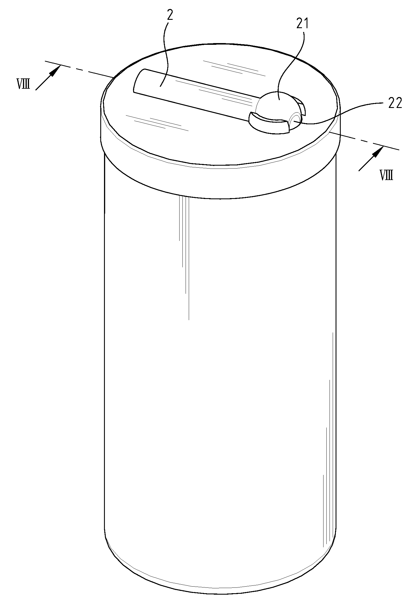
[0023]With reference to the drawings and in particular to FIG. 4, a cap with a suction unit for a cup in accordance with the present invention, comprises a cap 1 having a semi-spherical recess 11 defined in a top thereof, and an outlet 15 is defined through an inner end of the semi-spherical recess 11. At least one first air hole 13 is defined through the cap 1 and an inner periphery of the semi-spherical recess 11. Preferably, the at least one through hole 13 is defined in a lateral surface of the semi-spherical recess 11. An opening is defined in the top of the semi-spherical recess 11 and a diameter of the opening is smaller than a diameter of the semi-spherical recess 11. In a preferable embodiment, two flanges 12 extend from the top of the cap 1 and the opening is located between the two flanges 12. Each flange 12 includes an inner surface which has the same curvature as the semi-spherical recess 11. An elongate groove 14 is defined in the top of the cap 1, and the elongate gro...


PUM


Abstract

A cap with a suction unit includes a cap having a semi-spherical recess defined in a top thereof and communicating with an outlet defined through an inner end of the semi-spherical recess. A first air hole is defined through an inner periphery of the semi-spherical recess. A suction member has a spherical base, which is rotatably engaged with the semi-spherical recess, and a tube extends from the spherical base. A passage is defined through the spherical base and the tube. A second air hole is defined through the spherical base. The passage and the second air hole are respectively in communication with the outlet and the first hole when the suction member is pivoted to a first position, and the passage and the second air hole are respectively not in communication with the outlet and the air hole when the suction member is pivoted to a second position.

Description

BACKGROUND OF THE INVENTION[0001]1. Field of the Invention[0002]The present invention relates generally to a cap with a suction unit for a cup, and the suction unit is suitable to suck particulate food in the beverage.[0003]2. The Prior Arts[0004]A conventional beverage cup shown in FIGS. 1-3 generally includes a cap A, a suction member B and a cup C, in which the cap A includes a recess A1 and an elongate groove A3 defined in a top of the cap A, and the elongate groove A3 communicates with the recess A1. An outlet A5 is defined through the cap A and located in the recess A1, and two notches A2 are defined in two insides of the recess A1. An air hole A4 is defined through the cap A and located in the elongate groove A3. The suction member B includes a base B1 and two pivots B2 which are engaged with the two notches A2. A passage B4 is defined axially through the suction member B and a protrusion B3 extends from an outer periphery of the suction member B.[0005]As shown in FIG. 2, whe...

Claims


Application Information

Patent Timeline
Patent Type & Authority Applications(United States)
IPC IPC(8): A47G19/22
CPCB65D47/305A47G19/2266
Inventor HUNG, MING-HUA
Owner HUNG MING HUA
Why Eureka
Try Eureka