Valance apparatus

a technology of valances and brackets, applied in the field of valances, can solve the problems of not being able to effectively connect the two members, the gap between the two members is often visible, and the corners or other connectors of lightweight brackets, corners or other connectors, are often unable to effectively connect the relatively heavy valances

Inactive Publication Date: 2009-05-21
CHI GINA +2
View PDF19 Cites 10 Cited by
  • Summary
  • Abstract
  • Description
  • Claims
  • Application Information

AI Technical Summary

Benefits of technology

[0015]A kit which includes two or more valance side members, one or more valance front members and one or more valance component connectors is also provided. Each valance side member and the valance front member have a channel. The one or more valance component connectors include a first leg, a second leg and a rib extending from an intermediate portion of the first leg to an intermediate portion of the second leg. A first end of the first leg is adjacent the first end of the second leg such that the first leg is at a position that is substantially perpendicular to the second leg. The rib, first leg and second leg form a unitary structure.
[0016]In some embodiments of the kit, the one or more valance component connectors will also include adhesive that is covered by

Problems solved by technology

When brackets are used to connect a valance front member to a valance side member, a noticeable gap is often present between the two members.
However, we have recognized that

Method used


Image

  • Valance apparatus
  • Valance apparatus
  • Valance apparatus

Examples


Embodiment Construction

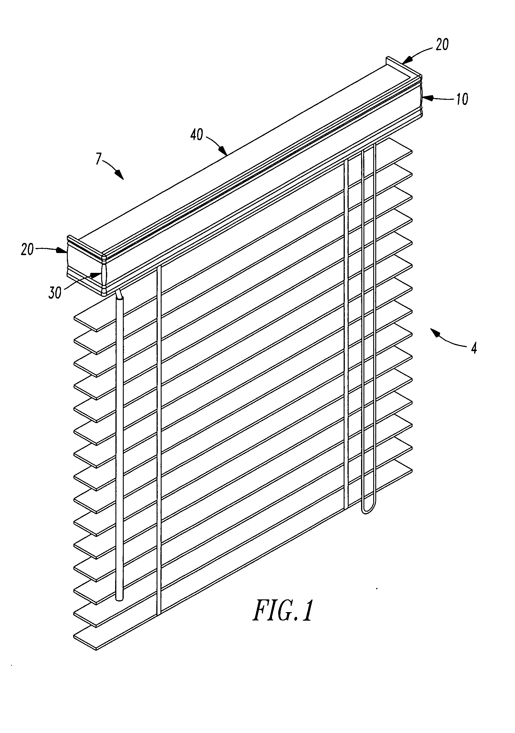
[0032]Referring to FIG. 1, a valance 7 formed from an embodiment of our valance kit frames the headrail 40 of a venetian blind 4. The valance 7 has a valance side member 20 connected to each end of a valance front member 10. A valance component connector 30 connects each side member 20 to the front member 10.

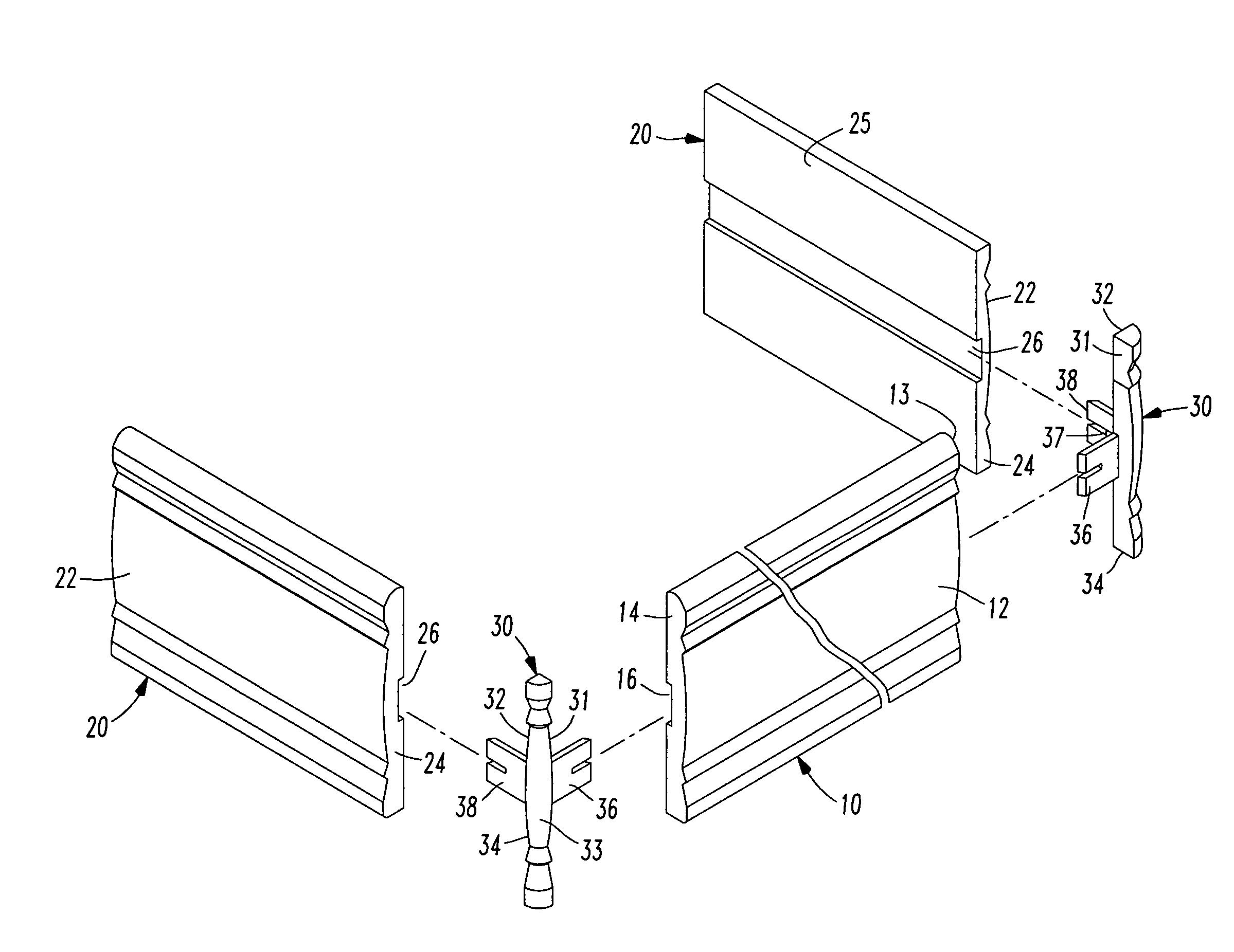
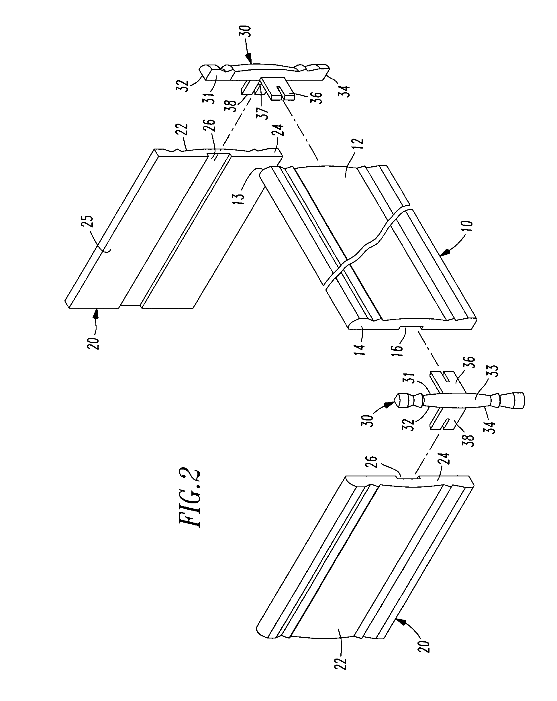
[0033]As best seen in FIGS. 2 and 3, a first present preferred embodiment of our valance kit includes a front valance member 10 that has a front surface 12, a first end 13, a second end 14 and a channel 16 formed within the back surface 15 of the valance front member 10. The channel 16 extends from the first end 13 to the second end 14. The front surface 12 may have a painted finish or a wood-grain finish. The front surface may also be contoured, as may best be appreciated from FIG. 2.

[0034]Two valance side members 20 are also provided. The valance side members 20 have a front surface 22 and at least one channel 26 formed in the back surface 25 of the valance side members 20. Th...


PUM


Abstract

A valance component that includes a first leg, a second leg, a rib extending between an intermediate portion of the first leg to an intermediate portion of the second leg and a member connected to the first and second legs is disclosed. The member has a first face that faces toward the first leg and a second face that faces toward the second leg. The member is sized and configured to be positioned between a valance side and a valance front member, which each have a groove sized to receive at least a portion of the first leg or the second leg. A kit is also disclosed that includes at least one of the valance components, two or more valance side members and at least one valance front member. The kit may include separately packaged components or components that are all retained within one package.

Description

CROSS REFERENCE TO RELATED APPLICATION[0001]This application claims priority to Taiwanese Patent Application No. 096219395, filed Nov. 16, 2007.FIELD OF INVENTION[0002]The present invention relates to valances for window coverings.BACKGROUND OF THE INVENTION[0003]Homeowners often use valances to conceal the headrail of a blind, the roller tube of a roller shade or other fixtures that may be located above a window or window opening. Examples of various valances are disclosed in U.S. Pat. Nos. 6,629,481, 4,828,002, 4,662,421, 3,574,887, 2,526,806, 2,501,133 and D379,729.[0004]Valances are typically mounted to a wall adjacent a window opening. Valances normally include a front member positioned in front of a headrail or other fixture and two side members that extend from the ends of the front member toward the wall surrounding the window opening such that the valance blocks the fixture from view. The valance side members are typically fastened to the ends of the valance front member by...

Claims


Application Information

Patent Timeline
IPC IPC(8): E06B9/24G06Q10/00
CPCE06B9/323A47H2/00
Inventor CHI, GINACHUANG, YI-SHENGCHEN, TUNG-JUNG
Owner CHI GINA
Why Eureka
Try Eureka