Sound attenuating air vent

a technology of air vents and sound attenuation, which is applied in the field of air vents, can solve the problems of increased air pressure in the room, restricted airflow, and increased load on the air-conditioning system

Inactive Publication Date: 2009-05-28
OWENS ROBERT LEE
View PDF13 Cites 29 Cited by
  • Summary
  • Abstract
  • Description
  • Claims
  • Application Information

AI Technical Summary

Problems solved by technology

The problem with this approach is that when doors are closed, the airflow is restricted.
This restricted airflow results in greater air pressure in the rooms, more load on the air-conditioning system, and more leakage of air through the windows and air ducts due to the higher pressure.
If this entry door is closed, it is unreasonable to expect that the crack between the bottom of the door and the floor would be sufficient to pass the necessary air.
However, return vents in each room would be much more expensive than one centrally located return vent.
Furthermore, the additional return ducts would not be feasible for limited space conditions, such as when the ducts must be located in the space between floors.
The problem with this approach is that the currently available vents allow sound to easily travel between rooms.
Sound easily traveling between rooms is unacceptable in many cases because it defeats the privacy reason for closing the doors between rooms.

Method used


Image

  • Sound attenuating air vent
  • Sound attenuating air vent
  • Sound attenuating air vent

Examples


Embodiment Construction

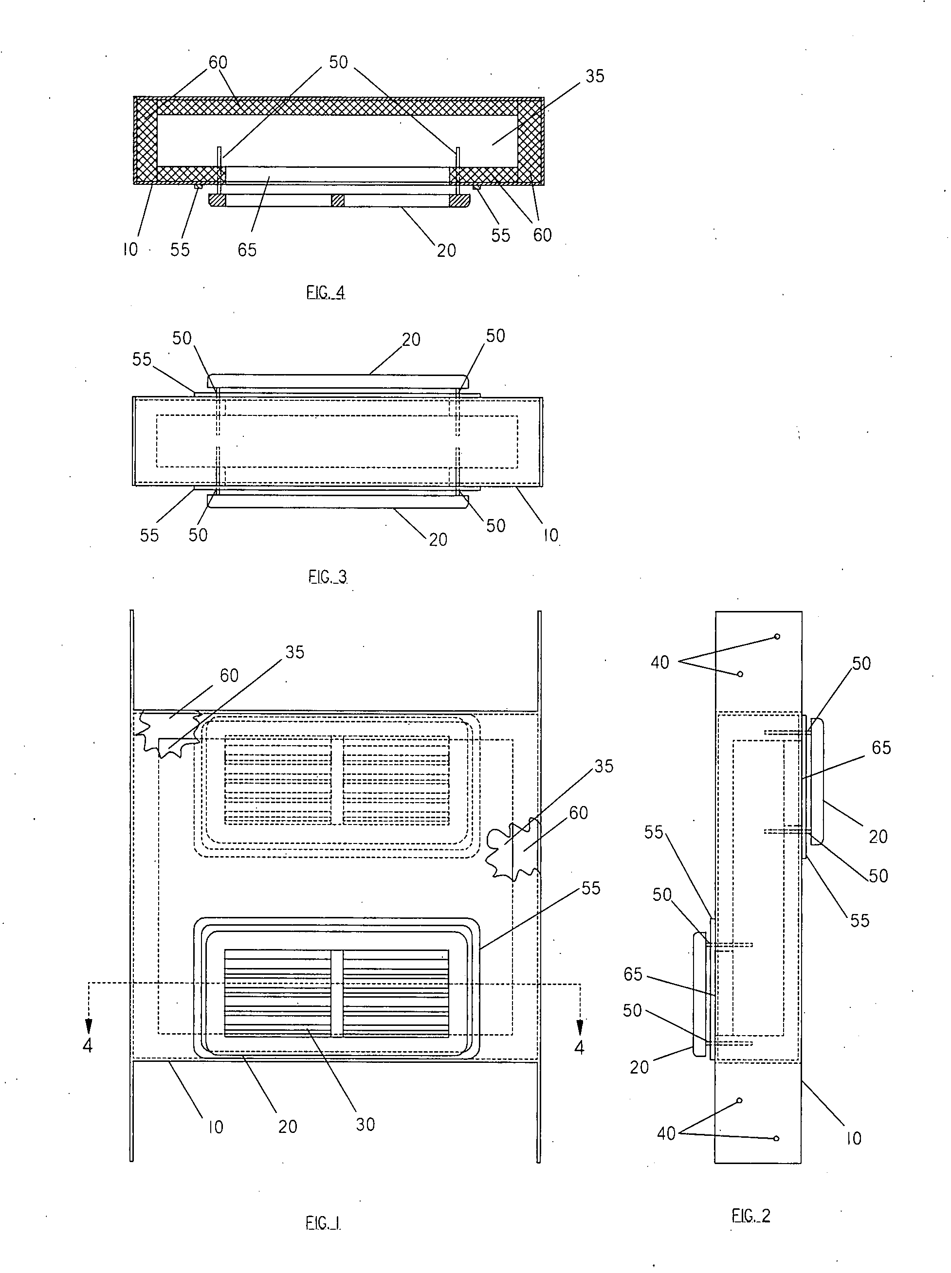
—FIGS. 1-4—PREFERRED EMBODIMENT

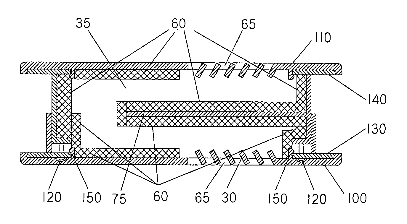
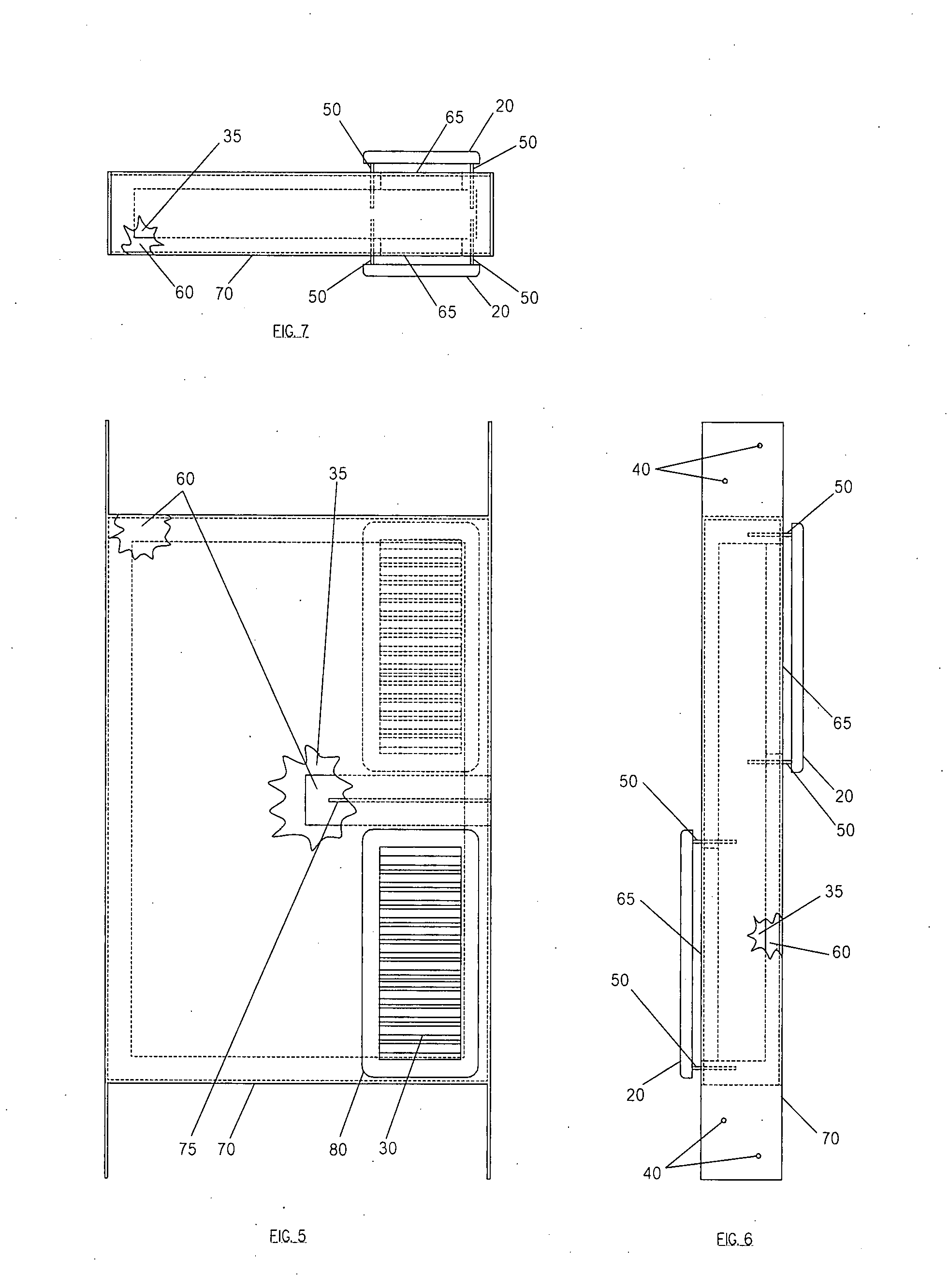
[0081]A preferred embodiment of the vent of the present invention is illustrated in FIG. 1 (front view), FIG. 2 (right view), FIG. 3 (top view), and FIG. 4 (section view). This vent 10 is intended to be installed during construction. After construction, the only visible parts would be the vent covers 20. Air would flow through the front vent cover 20, through the chamber 35 (i.e. interior of the vent), which would typically be covered with sound attenuating material 60, and finally out the back vent cover 20. In some cases, due to the convoluted pathway and the acoustical characteristics of the construction materials, the sound attenuating material 60 may not be necessary. The vent cover 20 has louvers 30 which allow air flow through the vent cover 20. The vent cover 20 is removable providing access for cleaning, and is held in place by attaching mechanisms 50. There are many forms of attaching mechanisms 50 that are typically used to hold vent covers ...


PUM


Abstract

An device that allows air flow while attenuating sound for the purposes of allowing air to flow between rooms in a structure such as a house or building. The device consists of an air passageway that attenuates sound and covers at each end of the passageway. The covers allow air flow while providing an aesthetically pleasing appearance. Multiple embodiments support pre and post construction scenarios as well access to the interior of the device for cleaning purposes.

Description

CROSS REFERENCE TO RELATED APPLICATIONS[0001]Disclosure Document #608522, Quiet VentFEDERALLY SPONSORED RESEARCH [0002]Not ApplicableSEQUENCE LISTING OR PROGRAM [0003]Not ApplicableBACKGROUND OF THE INVENTION[0004]1. Field of Invention[0005]This invention relates to air vents; specifically, air vents that allow air flow while attenuating sound.[0006]2. Background of the Invention[0007]A very common form of an air conditioning system for enclosed structures (i.e. houses / buildings) relies on the circulation of air. Air is pulled from the interior of the structure and passed through a heating / cooling air handler and then is returned to the interior of the structure. The air intake / return is usually a centrally located large vent attached to a large duct that feeds air to the air handler. The air handler forces air out smaller exhaust ducts that terminate in each room of the structure. In some cases, the rooms have multiple exhaust vents. The problem with this approach is that when door...

Claims


Application Information

Patent Timeline
Patent Type & Authority Applications(United States)
IPC IPC(8): F24F7/04E04F17/04
CPCF24F13/24E04F17/04
Inventor OWENS, ROBERT LEE
Owner OWENS ROBERT LEE
Why Eureka
Try Eureka