Brake device for prams

Inactive Publication Date: 2009-06-04
JANE SA
View PDF5 Cites 6 Cited by
  • Summary
  • Abstract
  • Description
  • Claims
  • Application Information

AI Technical Summary

Benefits of technology

[0002]This invention has as an object a brake device of the type wherein with one single control one is in a position to by means of ropes simultaneous

Problems solved by technology

The ropes are inferiorly linked to the wheel brake and biased by respective springs being provided for securing the brake-on position.

Method used


Image

  • Brake device for prams
  • Brake device for prams

Examples


Embodiment Construction

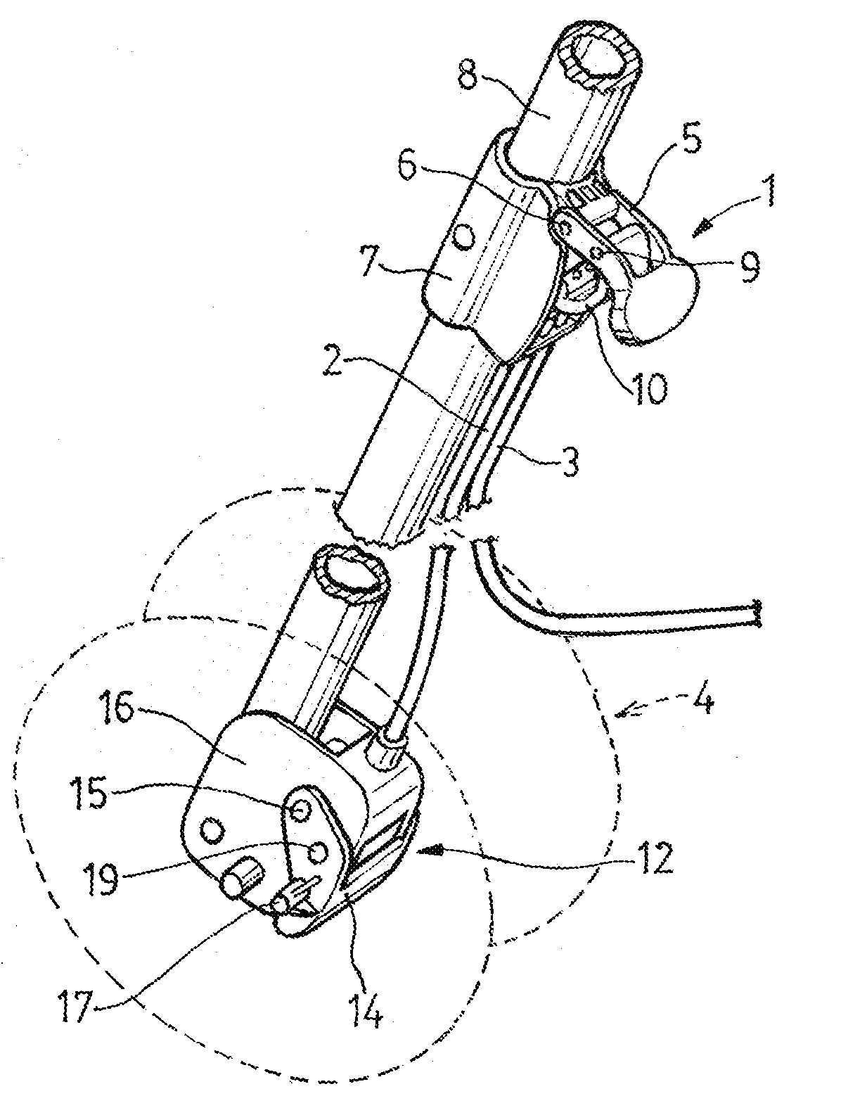
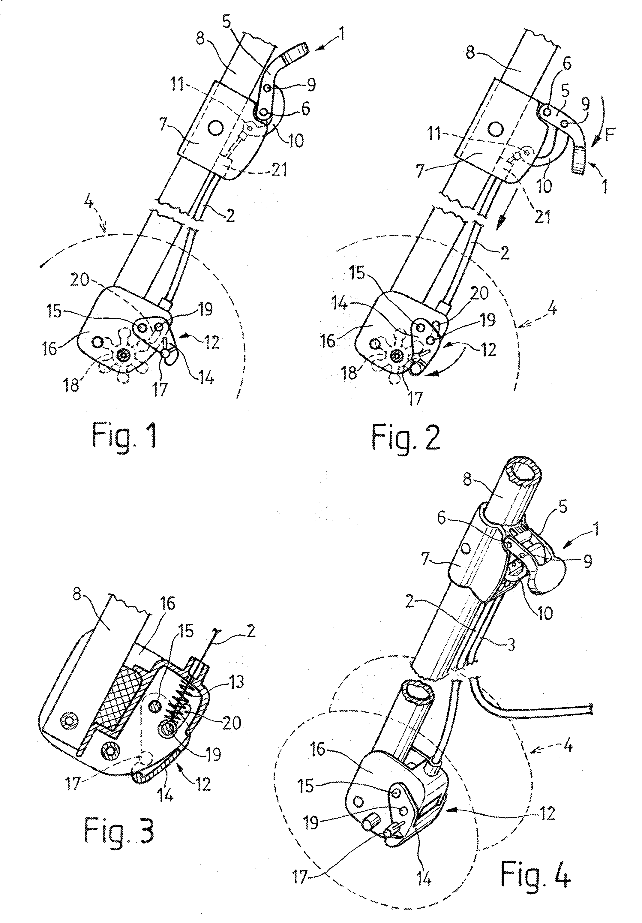
[0010]According to the drawings the brake device acts on dual wheels and has a single control (1) that by sheathed ropes (2 and 3) and in a simultaneous manner acts on each of the two double wheels (4) being arranged at each side of the pram.

[0011]The control (1) has an angular, hand-operated lever (5) being at its end linked in a pin-jointed connection by the pin (6) to a bracket (7) being securedly attached to one of the rear legs (8) of the pram.

[0012]This lever (5) has two positions namely being a passive one (FIG. 1) wherein the device is in the brake-off position, and an active one (FIGS. 2 and 4) wherein the device is in the brake-on position.

[0013]At an intermediary point (9) of the lever (5) an arm (10) is linked in a pin-jointed connection, the arm at its free end (11) having the sheathed ropes (2 and 3) linked to it, these latter being inferiorly linked to the wheel brake (12) and biased by respective springs (13) being in a position to secure the brake-on position (FIG. ...


PUM


Abstract

This device is actuated by a single control (1) that by ropes (2 and 3) and in a simultaneous manner acts on the rear wheels (4) of the pram. The control (1) has a lever (5) at its end (6) being linked to a bracket (7) in a pin-jointed connection and at an intermediary point (9) being inferiorly linked in a pin-jointed connection to an arm (10) being at its free end (11) linked to the ropes (2 and 3). The ropes are inferiorly linked to the brake ans (12) being operable for braking the wheels (4), the ropes being biased by respective springs (13) provided for securing the brake-on position. The control lever (5) in its raised brake-off position is stabilized in a position beyond vertical where it is maintained by the pulling force of the springs (13).

Description

BACKGROUND OF THE INVENTION[0001]As is known, all prams have brakes generally acting on the rear wheels, some of those brakes having a separate control element for each wheel whereas in some cases one single control has been provided for simultaneously acting on the two brakes corresponding to either side of the pram, said action being carried out through mechanical elements or else by means of ropes.SUMMARY OF THE INVENTION[0002]This invention has as an object a brake device of the type wherein with one single control one is in a position to by means of ropes simultaneously act on the two lateral wheels, said brake device having a simple make-up while at the same time being in a position to act in a very positive manner.[0003]The single control is made up by a lever being easily accessible for its manual actuation, said lever at its end being linked to a bracket in a pin-jointed connection and at an intermediary point being inferiorly linked in a pin-jointed connection to an arm be...

Claims


Application Information

Patent Timeline
IPC IPC(8): B62B9/08
CPCB62B9/082B62B5/0438B62B9/087
Inventor SANTAMARIA, MANUEL JANE
Owner JANE SA
Why Eureka
Try Eureka