Pre-grinder or pre-shredder

Active Publication Date: 2015-08-11
AG BECKER & CO +2
View PDF10 Cites 1 Cited by
  • Summary
  • Abstract
  • Description
  • Claims
  • Application Information

AI Technical Summary

Benefits of technology

The invention proposes a pre-grinder or pre-shredder that can solve issues of bulk and weight and adapt to different processing capacities. It has a simple make-up and low production cost.

Problems solved by technology

The processing of very bulky objects or materials necessitates the use of grinders or crushers of large size and high power and therefore with a very high production cost as well as a very high cost of use.
Furthermore, the shredding tools are mounted generally by welding on the large cross-section drive shaft and are therefore not interchangeable.
The mounting of these large-sized pieces of equipment, namely reducing gears and motors, outside of these machines has as a result a considerable space requirement of the latter, which is incompatible with a small-capacity processing unit, which must, in essence, be mobile for its possible use on different sites.
Moreover, the motors used are most often hydraulic motors, which are slow, very heavy and mounted freely on the ends of the shafts, or even electric or hydraulic motors connected to said shafts by ordinary reducing gears or planetary gears.
The making of such grinders or pre-shredders is very expensive, and the machines made in this way are very bulky and very heavy.
Consequently, using such a device is very expensive necessitating, in fact, the provision of complete, interchangeable grinding chambers, the service actions then being performed in idle time.
Such an embodiment obviously makes it possible to reduce the bulk of the rotor assembly of the grinder and drive motor, but necessitates significant and costly disassembly work that is incompatible with the making of low-cost grinders or pre-grinders that are quick and simple to use.

Method used


Image

  • Pre-grinder or pre-shredder
  • Pre-grinder or pre-shredder
  • Pre-grinder or pre-shredder

Examples


Embodiment Construction

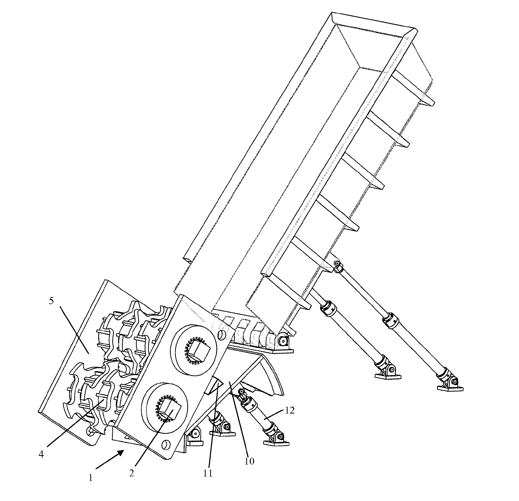
[0026]FIG. 1 of the accompanying drawings shows, by way of example, a pre-grinder or pre-shredder intended to be used in the field of the processing of materials of all origins, in particular by shredding by means of crushers or of hammer mills, or the like.

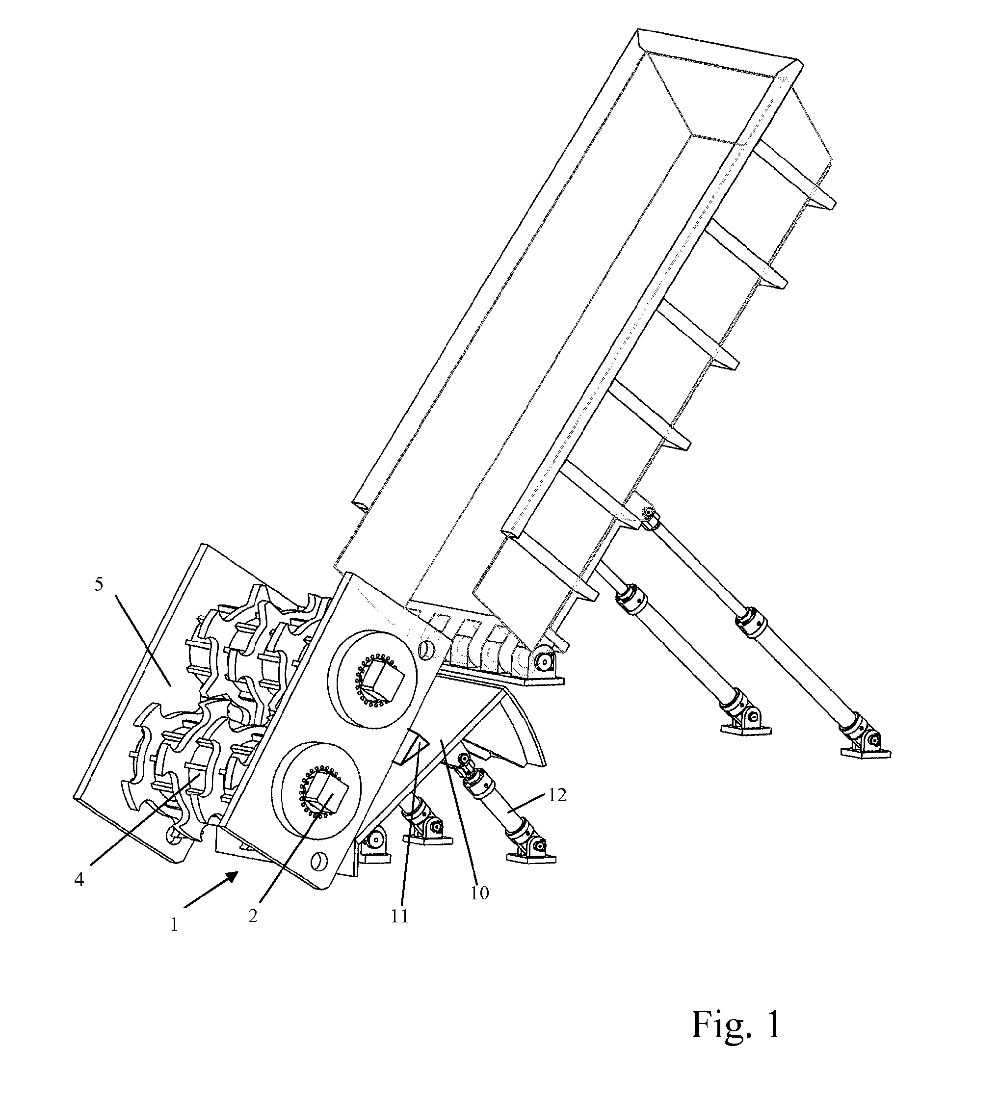
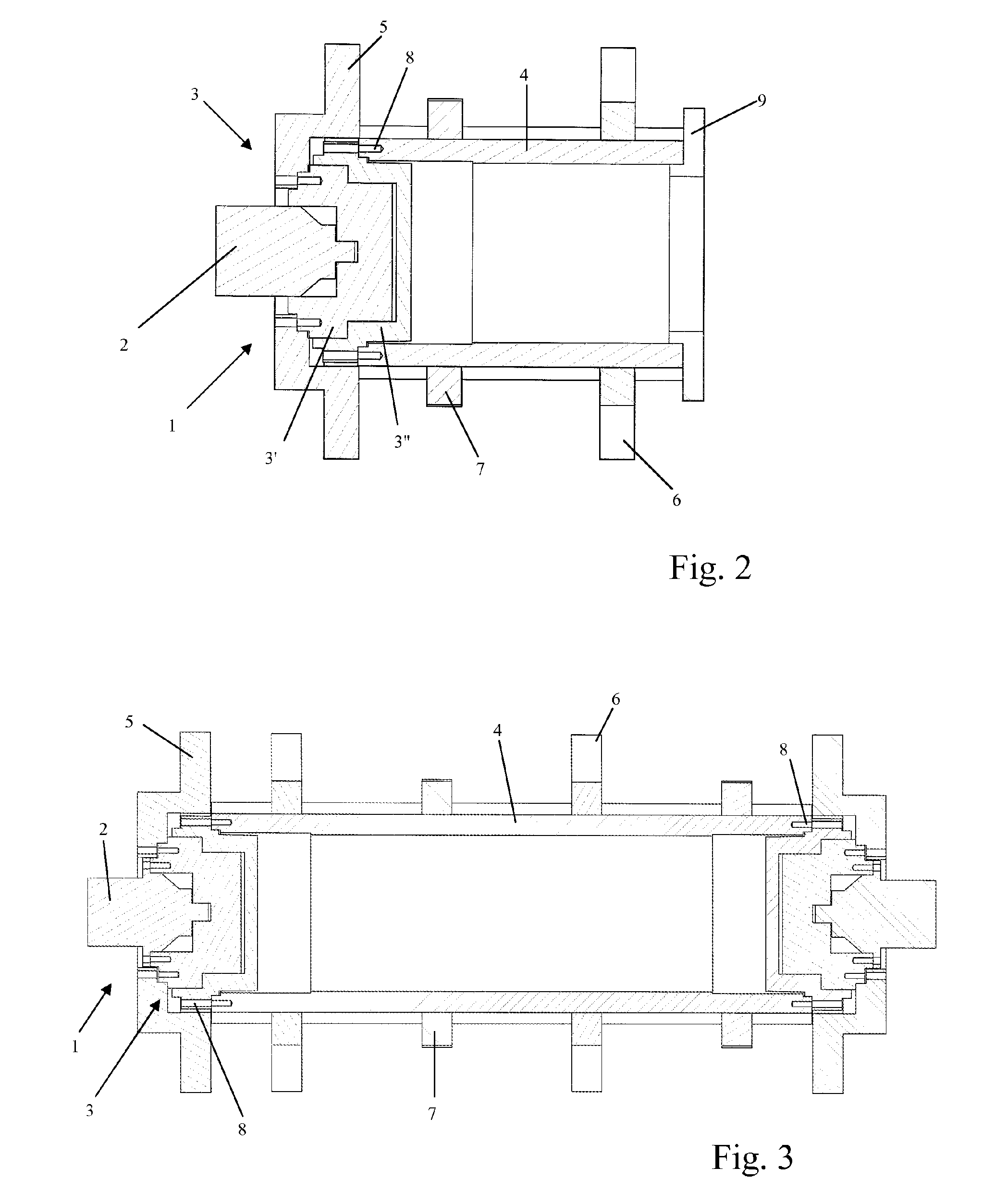
[0027]Such a pre-grinder or pre-shredder essentially consists of at least one drive assembly 1 comprising a hydraulic or electric drive motor 2 and a reducing gear 3 and of at least one shredding element 4 connected to the reducing gear 3, and is mounted on a frame 5, a feeding chute or another support (FIG. 1). In a known way, such a pre-grinder or pre-shredder can be mounted upstream from a crusher or grinder and feeds directly, at its output, said crusher or grinder.

[0028]According to the invention, the reducing gear 3 of the drive assembly 1 of this pre-grinder or pre-shredder forms a fastening and support element of at least one shredding element 4, and consists of a stationary part 3′, fastened directly to the frame 5 of th...


PUM


Abstract

A pre-grinder or pre-shredder apparatus, essentially made up of at least one drive unit (1) including a hydraulically or electrically driven motor (2), a reduction gear (3) and at least one shredding element (4) connected thereto and mounted on a frame (5), a wall, a feeder chute or any other mounting. The reduction gear (3) of the drive unit (1) of the pre-grinder or pre-shredder forms an element for attaching and supporting at least one shredder element (4) and is made up of a stationary portion (3′), attached directly to the frame (5) of the pre-grinder or pre-shredder or on a mounting or a wall of the latter, and by a mobile portion (3″), the shredder element (4) being inserted on the mobile portion of the reduction gear. The apparatus is useful in treating materials from any source, in particular by shredding using grinders, hammer mills or similar devices.

Description

BACKGROUND OF THE INVENTION[0001]1. Field of the Invention[0002]This invention relates to the field of processing materials of all origins, in particular by shredding by means of crushers or of hammer mills, or the like, and has as its object a pre-grinder or pre-shredder.[0003]2. Description of the Related Art[0004]The recovery of metal products from objects that are unserviceable, in particular motor vehicles, by means of crushers or grinders, is generally performed by introducing the objects in a hammer mill, via an introduction ramp equipped with a crushing drum; said hammer mill pulls and shreds the material entering there, by interaction with one or more anvils, which eject and / or evacuate, through screening walls, the mechanical scraps obtained that exhibit a determined size. These scraps are then processed for the purpose of eliminating materials that are unsuitable for reuse and for the purpose of sorting the remaining materials as a function of their metallurgical characte...

Claims


Application Information

Patent Timeline
IPC IPC(8): B02C18/06B02C18/24B02C13/286B02C13/30B02C13/20B02C4/42B02C18/30
CPCB02C13/286B02C13/30B02C13/20B02C18/24B02C2018/307B02C4/42
Inventor BECKER, ARNAUDBECKER, CAROLINEBECKER, CATHERINE
Owner AG BECKER & CO
Why Eureka
Try Eureka