Support for an elevator installation

a technology for installing supports and elevators, which is applied in the direction of elevators, mine lifts, transportation and packaging, etc., can solve the problems of affecting affecting the safety of elevators, so as to simplify the electrical contact of tensile carriers, less complicated, and less susceptible to errors

Inactive Publication Date: 2018-05-29
INVENTIO AG
View PDF13 Cites 2 Cited by
  • Summary
  • Abstract
  • Description
  • Claims
  • Application Information

AI Technical Summary

Benefits of technology

[0010]Such a method for provision of a support means for use in an elevator installation has the advantage that the support means pre-prepared in that manner can at the time of installation in an elevator installation be connected in simple, reliable and economic mode and manner with a monitoring device. Thus, when the support means is installed in the elevator installation there is no need for special tools or work sequences which can be difficult to check. The installation time of an elevator installation can thereby be reduced and at the same time the quality of the electrical contacting of the tensile carriers improved, because there are no working steps susceptible to error. In addition, the make-up of assembly personnel can be simplified, since there are no complicated working steps.
[0026]In an exemplifying form of embodiment at the time of installation of the support means in the elevator installation the support means is fastened in such a manner to the support means fastening devices that an excess length of the support means is stored substantially behind only one support means fastening device. This has the advantage that the excess length has to be stored only once in the elevator installation. This reduces cost at the time of installation of the support means in the elevator installation. In an advantageous development the excess length of the support means is rolled up and fastened to a support.

Problems solved by technology

Failure or breakage thereof can lead to substantial harm to objects or persons.
It can be disadvantageous in that case that the contact elements due to the required puncturing process through the casing miss the tensile carriers.
In addition, a transfer resistance between the tensile carriers and the contact elements penetrated therein can change over time which has a disadvantageous effect on the meaningfulness of a monitoring procedure.
It is disadvantageous with such contacting systems that the connection between contact elements and tensile carriers is non-constant and that a high transfer resistance between the contact element and the tensile carriers is present.

Method used


Image

  • Support for an elevator installation
  • Support for an elevator installation
  • Support for an elevator installation

Examples


Embodiment Construction

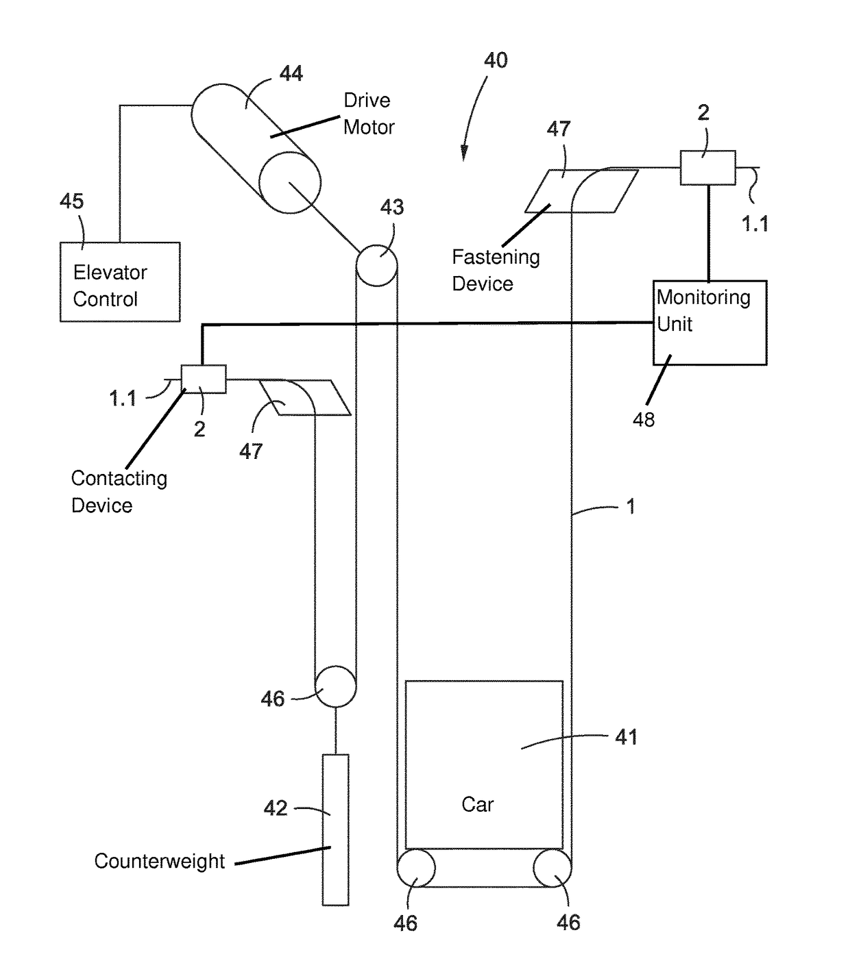
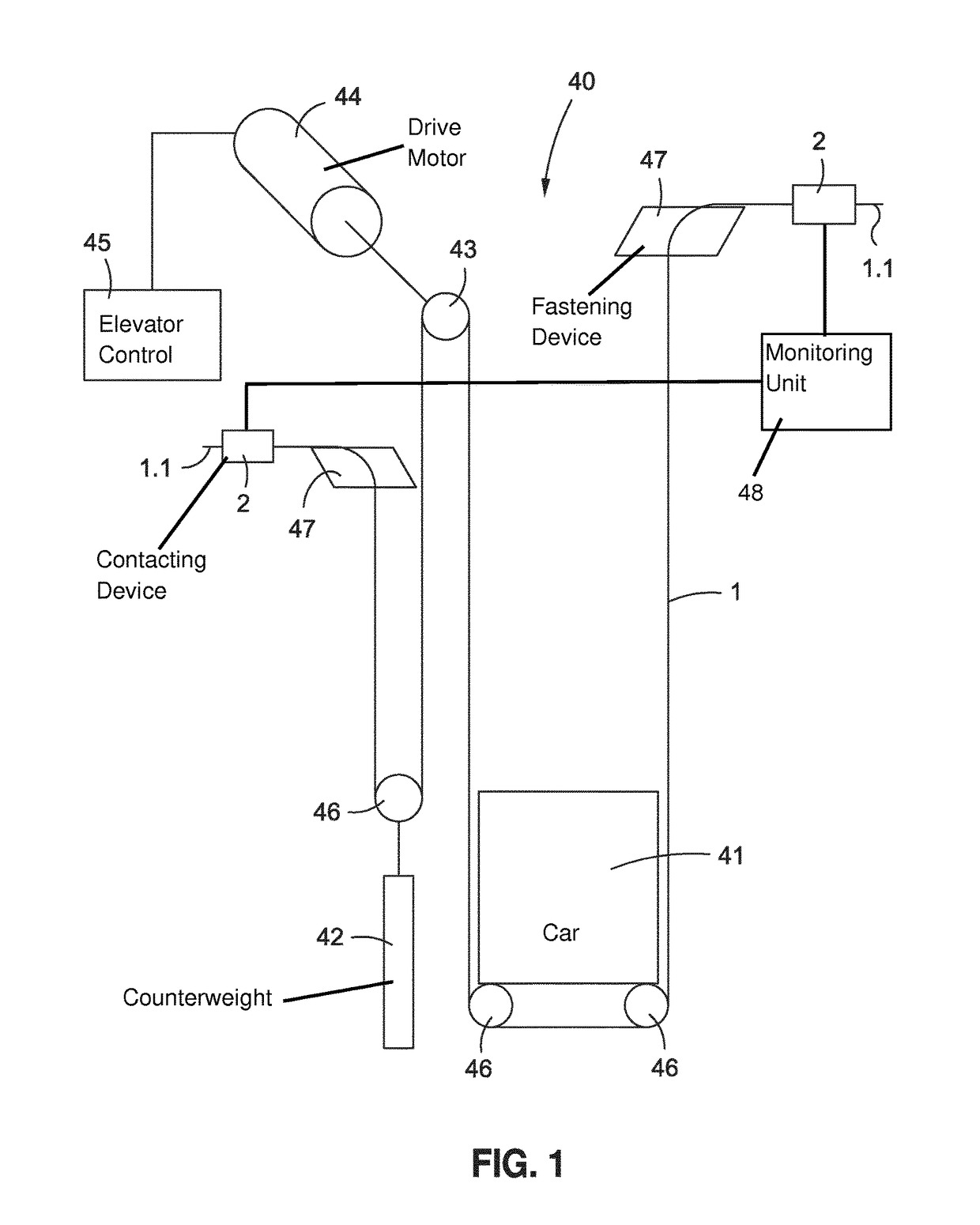
[0037]The elevator installation 40 illustrated schematically and by way of example in FIG. 1 includes an elevator car 41, a counterweight 42 and a support means 1 as well as a drive pulley 43 with associated drive motor 44. The drive pulley 43 drives the support means 1 and thus moves the elevator car 41 and the counterweight 42 in opposite sense. The drive motor 44 is controlled by an elevator control 45. The car 41 is designed to receive persons and / or goods and to transport them between floors of a building. The car 41 and counterweight 42 are guided along guides (not illustrated). In the example the car 41 and the counterweight 42 are each suspended at support rollers 46. The support means 1 is in that case fixed at a first support means fastening device 47 and then guided initially around the support roller 46 of the counterweight 42. The support means 1 is then laid over the drive pulley 43, guided around the support rollers 46 of the car 41 and finally connected by a second s...


PUM


Abstract

A method of providing a support for an elevator car in an elevator installation, wherein the support includes a plurality of tensile carriers arranged parallel to one another and substantially enclosed by a casing, includes pre-preparation of a first support end wherein the tensile carriers are directly electrically contactable at a pre-prepared location by a contacting device, and wherein the pre-preparation is carried out before transport of the support to the elevator installation.

Description

FIELD[0001]The subject of the invention is a method for providing a support means for use in an elevator installation.BACKGROUND[0002]In many conveying devices such as, for example, elevator installations, cranes or hoists use is made of belt-shaped support means. These support means generally comprise a plurality of tensile carriers which consist of steel wires and which accept the tensile forces to be absorbed by the support means. The tensile carriers are generally surrounded by a casing of synthetic material. The casing protects the tensile carriers from, for example, mechanical wear, since the support means are frequently guided around deflection points. In addition, the casing improves the traction of the support means on deflecting or drive rollers and fixes the arrangement of the tensile carriers relative to one another.[0003]Such support means are a safety-relevant component within a conveying device. Failure or breakage thereof can lead to substantial harm to objects or pe...

Claims


Application Information

Patent Timeline
Patent Type & Authority Patents(United States)
IPC IPC(8): B66B1/34B66B5/00B66B7/06B66B19/02B66B3/00B66B7/12B66B7/08
CPCB66B19/02B66B5/0031B66B7/1223B66B7/08B66B7/062
Inventor DOLD, FLORIAN
Owner INVENTIO AG
Why Eureka
Try Eureka