
Variable-duct support assembly

Inactive Publication Date: 2005-09-29
THE BOEING CO
View PDF31 Cites 37 Cited by
  • Summary
  • Abstract
  • Description
  • Claims
  • Application Information

AI Technical Summary

Benefits of technology

[0006] One advantage of the invention is that a variable-duct support assembly is provided that can distribute a load substantially across the surface of a duct and decrease the likelihood of inadvertently deforming the ducts during installation of the ductwork.
[0007] Another advantage of the invention is that a variable-duct support assembly is provided that has a robust and common construction for mounting ducts of various shapes and sizes thereon, which decreases installation time and minimizes labor costs associated therewith.
[0008] Still another advantage of the invention is that a variable-duct support assembly is provided that can eliminate the need for new tooling associated with new configurations, e.g. differently shaped or sized ducts.
[0009] Yet another advantage of the invention is that a variable-duct assembly is provided that has substantially few parts thereby simplifying the manufacture of the assembly, decreasing the costs associated therewith, and improving the installation of ducts onto the assembly.
[0010] The features, functions, and advantages can be achieved independently and in various embodiments of the present invention or may be combined in yet other embodiments.

Problems solved by technology

Moreover, each support assembly can be comprised of a substantial number of parts and have a somewhat complex construction.
In this way, these support assemblies can result in expensive material costs, lengthy installation times, and high labor costs associated therewith.
This condition can require new tooling and further increase the time required to install the ductwork.

Method used


Image

  • Variable-duct support assembly
  • Variable-duct support assembly
  • Variable-duct support assembly

Examples


Embodiment Construction

[0026] In the following figures the same reference numerals will be used to illustrate the same components in the various views. The embodiments described herein employ features where the context permits, e.g. when a specific result or advantage of the claimed invention is desired. However, a variety of other embodiments are contemplated having different combinations of the described features, having features other than those described herein, or even lacking one or more of the described features. Specifically, the embodiments described herein implement a variable-duct support assembly for installing ductwork in an aircraft. Yet, it is contemplated that the variable-duct support assembly can be utilized for various other suitable applications and environments, e.g. other vehicles and buildings. For these reasons, it is understood that the invention can be carried out in various modes.

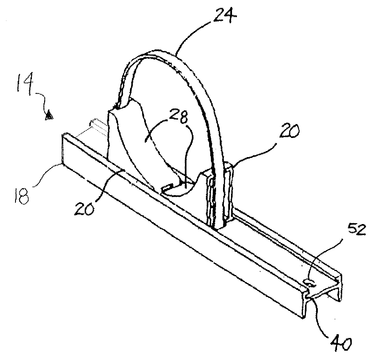
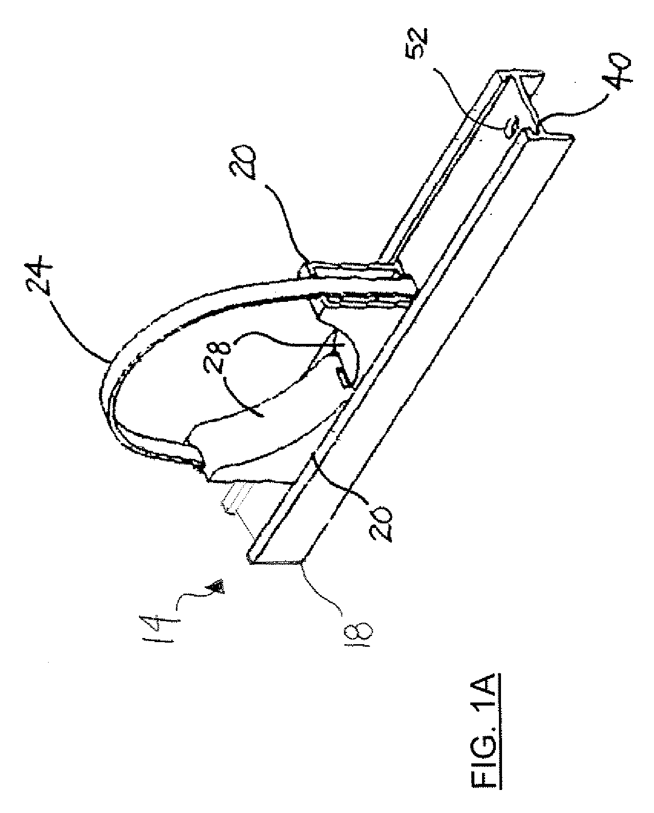
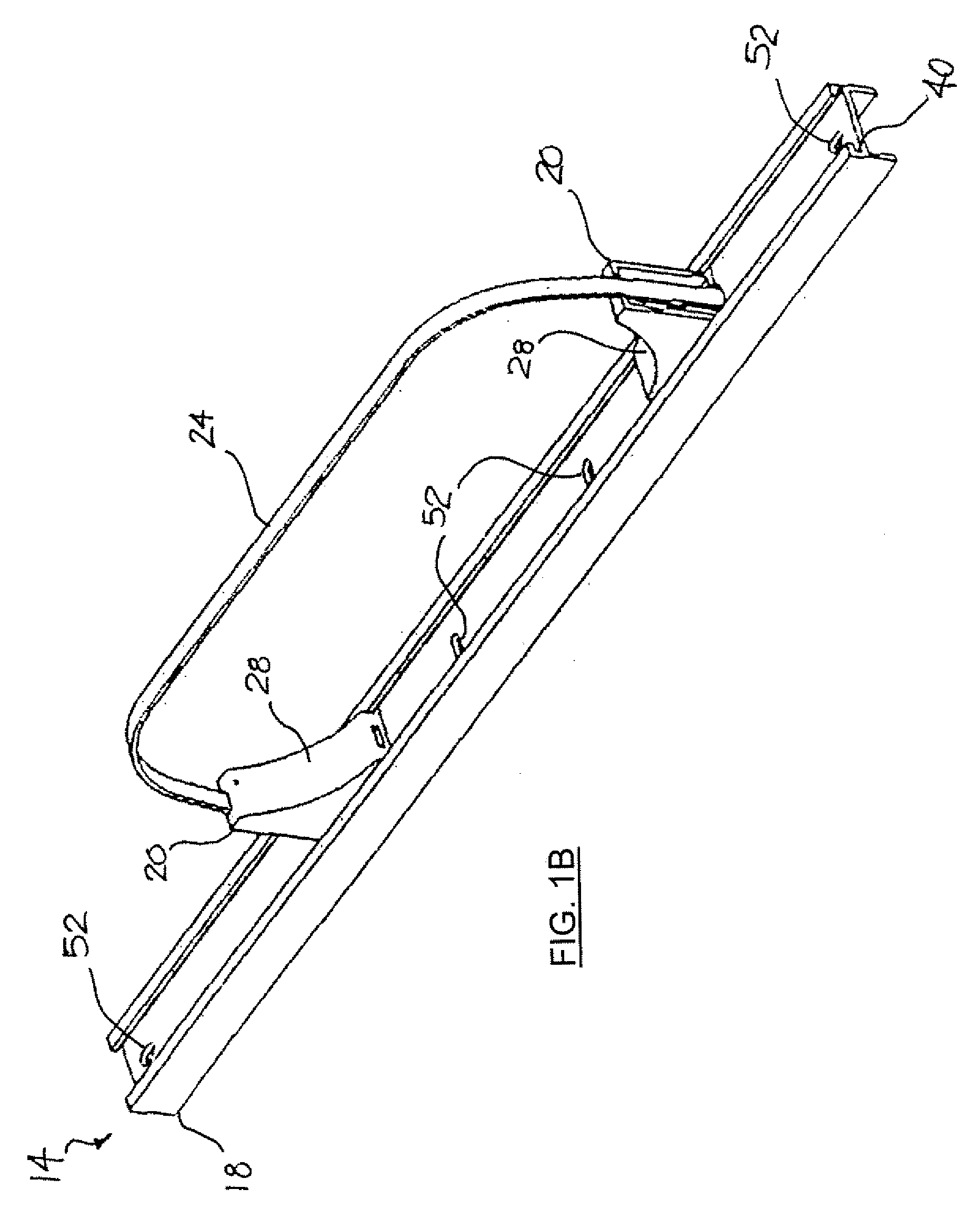
[0027] Referring to FIGS. 1A and 1B, there respectively are shown perspective views of a variable-d...


PUM


Abstract

One advantageous embodiment of the present invention is a variable-duct support assembly (14) for mounting one or more ducts (12a-12c) thereon. This variable-duct support assembly (14) includes one or more rails (18) each having a groove (40). Each groove (40) has one or more pairs of support brackets (20) positioned therein for supporting a proximal surface (22) of the ducts (12a-12c). The support brackets (20) are coupled to one or more flexible bands (24) and utilized for clamping the duct (12a-12c) between the support brackets (20) and the flexible bands (24). The flexible bands (24) are intended to contact and wrap around a distal surface (26) of the duct (12a-12c) so as to distribute a load substantially across the distal surface (26). Likewise, the support brackets (20) each include support portions (28) for distributing the load substantially across the proximal surface (22) of each duct (12a-12c).

Description

BACKGROUND OF INVENTION [0001] The present invention relates generally to ductwork, and more particularly to a variable-duct support assembly for mounting ducts of various shapes and sizes onto an airframe or other suitable structures. [0002] Aircraft manufacturers are well known for producing aircrafts having HVAC systems or various other systems with ductwork integrated therein. This ductwork typically is comprised of a series of cylindrical tubing or ducts for passing air throughout the aircraft. Typically, each duct requires a plurality of support assemblies for mounting the duct to the airframe of the aircraft. Moreover, each support assembly can be comprised of a substantial number of parts and have a somewhat complex construction. In this way, these support assemblies can result in expensive material costs, lengthy installation times, and high labor costs associated therewith. [0003] Additionally, existing support assemblies can be sized for mounting only specific ducts of ce...

Claims


Application Information

Patent Timeline
IPC IPC(8): B62D1/16F16L3/233F16L3/24
CPCF16L3/233F24F13/0254F16L3/24F16L3/243F16L3/245H02G3/32
Inventor PATTIE, JODY H.KING, TODD
Owner THE BOEING CO
Learn More