Windmill cable system and method

a windmill and cable technology, applied in the direction of coupling device connections, machines/engines, mechanical equipment, etc., can solve the problems of prohibitively difficult and dangerous for construction crews to hoist and mount such heavy cables, difficult and time-consuming splicing operations, and difficult and time-consuming to apply to a dense configuration of relatively stiff cable ends. , to achieve the effect of reducing the amount of tortional force, enhancing the ability of the cable, and reducing stress

Inactive Publication Date: 2006-09-07
RENEWABLES ENG SERVICES GROUP +1
View PDF9 Cites 40 Cited by
  • Summary
  • Abstract
  • Description
  • Claims
  • Application Information

AI Technical Summary

Benefits of technology

[0009] The electrical connectors forming the electrical connector assemblies may be detachably coupled by a mechanical interference coupling, such as a bayonet-type coupling that interlocks the connectors together when they are mated and twisted relative to one another. Preferably, when bayonet-type couplings are used, they are capable of interlocking when mated and twisted no more than 45° relative to one another to minimize the amount of tortional force necessary to interlock the power cables together. A ratchet lock is preferably provided in the bayonet-type coupling for preventing the coupling from being detached after the electrical connectors forming the assemblies are interlocked.
[0010] Whether the mechanical interference coupling takes the form of a bayonet-type coupling or not, it is preferably that the coupling allows done electrical connector to rotate at least 20° with respect to the connector it is coupled to in response to tortional forces applied to the cable. Such a feature advantageously allows the electrical connector assembly to accommodate, in a stress-reducing fashion, the tortional forces which are applied in particular to the upper portion of the power cables joining the generator to the first bundle of power cables located at the top of the base.
[0011] The power cables are preferably formed from a spirally-wound bundle of conductive wires, such as copper, covered by a flexible, elastomeric electrical insulator. To render the cables less more accommodating to the tortional forces which are applied to them during the oscillation of the head assembly of the windmill, the individual wires forming the conductive portion of the cable are all preferably helically wound in a same direction, i.e. either all left handed or all right handed. Such a structure enhances the ability of the cable to comply with torsional forces with reduced stress on the electrical connector assemblies.
[0012] Each of the electrical connector assemblies includes a water proof sleeve preferably formed from first and second mating sleeves circumscribing the two electrical connectors forming the assembly. These sleeves preferably detachably join in a water tight seal. To minimize the possibility of water incursion, each of the mating sleeves are preferably integrally formed on one end from the same insulation material circumscribing the helically wound wire conductors of the cable. The integrally formed end of each of the sleeves may include a stress relief portion for relieving bending stress on the wire conductors within the cable.
[0013] The cable system further includes first and second groups of control cables for supplying power to control systems of the electrical generator which are likewise formed into bundles and mounted along the inside walls of the base sections forming the support base of the windmill. Adjacent ends of the control cable bundles also preferably include electrical connectors that are detachably connectable to form electrical connector assemblies. Waterproof sealing structures are also included in these electrical connectors to prevent arcing and corrosion.

Problems solved by technology

However, in view of the long length of the power cables necessary to span the 60-100 meter height of the support base 3 of such windmills, it proved prohibitively difficult and dangerous to the construction crew to hoist and mount such heavy cables into the configuration indicated in FIG. 1B.
While such a cable system was a vast improvement over the previous “hoist and mount” system, the applicant has observed a number of problems and shortcomings associated with it.
First of all, the splicing operation has proven to be difficult and time consuming.
Such splicing machines weight on the order of 18 kilograms, and are difficult and time consuming to apply to a dense configuration of relatively stiff cable ends while suspended in midair.
Secondly, the resulting splices have proved to have an unacceptably high failure rate, despite the fact that the splicing machine squeezes the aluminum cups over the bare ends of adjacent cables at pressure of over 10,000 psi, and despite the diligence of skilled workers in applying insulating sleeves over the resulting splice.
Also, water can gradually accumulate in crevices formed by improperly applied insulating sleeves.
The combination of such gaps and / or moisture has led to arcing severe enough to set fire to the insulation surrounding the cables.
Finally, when such accidents have occurred, the hard-wired characteristics that such splices give to the power cable system have made it difficult and time consuming to replace sections of burned power cables.

Method used


Image

  • Windmill cable system and method
  • Windmill cable system and method
  • Windmill cable system and method

Examples


Embodiment Construction

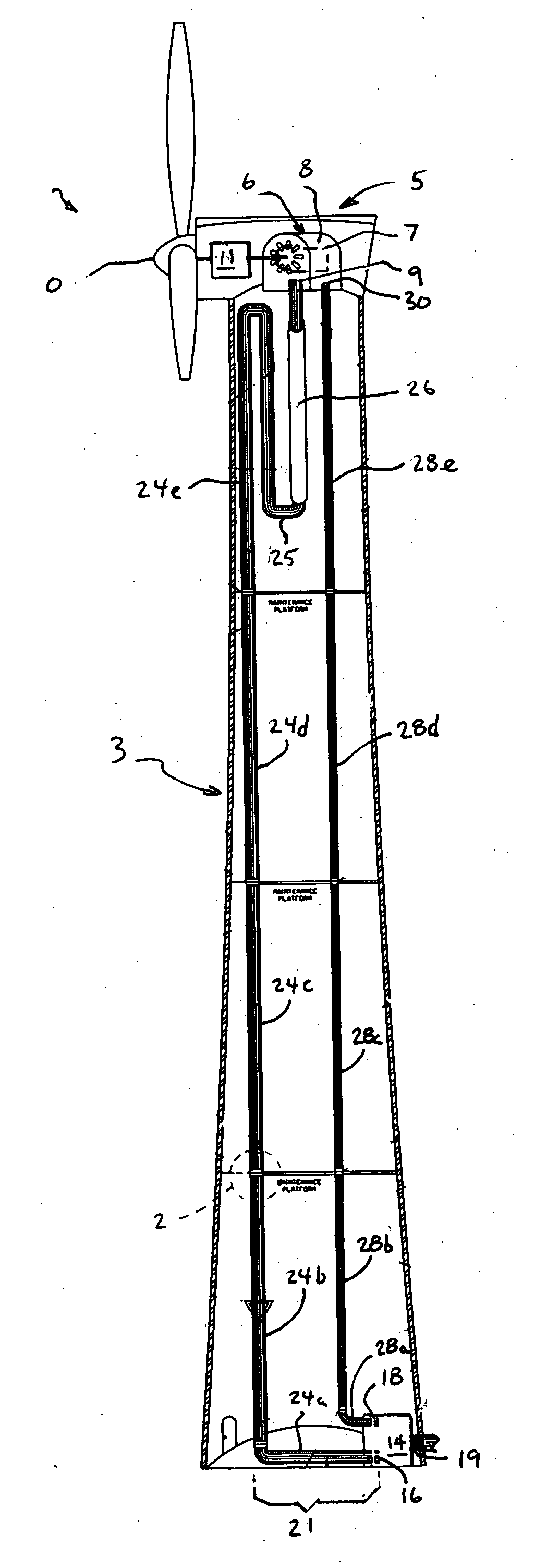
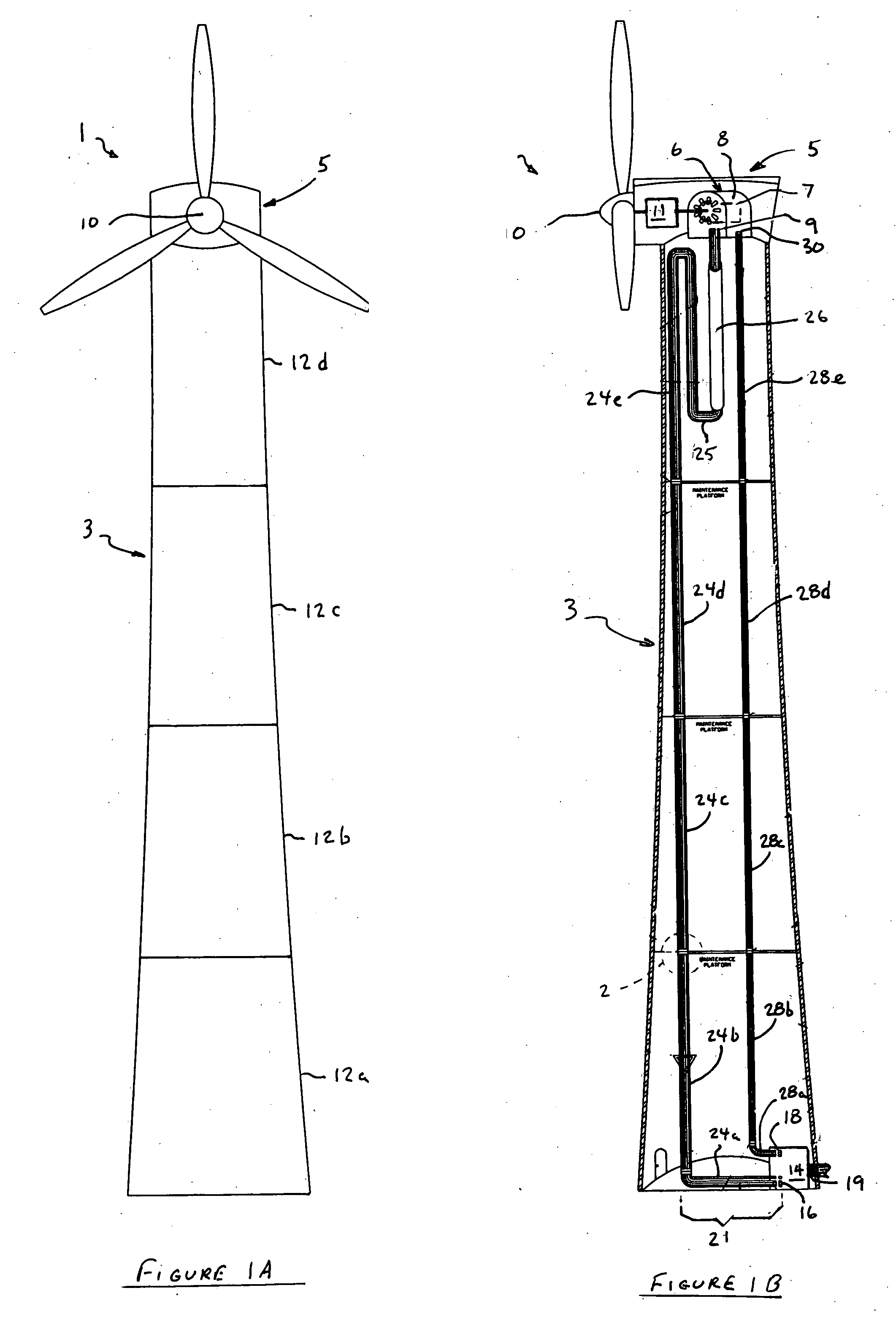
[0021] With reference now to FIGS. 1A and 1B, wherein like numerals designate like components throughout all the several figures, the electricity generating windmill 1 that the cable system of the invention is applicable generally to includes a support base 3 having a head assembly 5 oscillatorily mounted at the top thereof.

[0022] The head assembly 5 houses a DC generator 6 having a rotor 7 and stator 8, as well as power outlet terminal 9. The head assembly 5 further includes a blade assembly 10 driven by ambient wind. A gear train 11 couples the output shaft of the blade assembly 10 to the input shaft of the DC generator 6.

[0023] The support base 3 is formed from a plurality of stacked base sections 12a-12d. An inverter circuit 14 is disposed in the interior of the support base 3 at its bottom. The inverter circuit 14 includes an inlet terminal 16 for receiving direct current produced by the generator 6 and converting it into alternating current. The inverter circuit 14 further i...


PUM


Abstract

An improved cable system and method for an electricity generating windmill having a base formed from a plurality of stacked base sections is provided. Each base section includes a bundle of both power and control cables which are alignable with one another when the base sections are stacked and assembled. Mating electrical connectors which may be easily interlocked are provided at the ends of the power and control cables, and in the terminals of the generator and inverter of the windmill. In the preferred embodiment, bayonet-type connectors are used to provide a secure, interlocking coupling between adjacent cable ends with a minimum amount of twisting motion between the cables, which are necessarily of heavy gauge to conduct the current produced by the generator. The system greatly facilitates installation of the cable system as well as repair or replacement of damaged or worn cables during the lifetime of the windmill.

Description

FIELD OF THE INVENTION [0001] This invention generally relates to electrical cable systems, and is specifically concerned with an improved power cable system for an electricity generating windmill. BACKGROUND OF THE INVENTION [0002] While windmills per se have been in existence for over one thousand years, electricity generating windmills capable of producing power on the order of several megawatts are a relatively recent development. The general structure of such a modern, power generating windmill is illustrated in FIGS. 1A and 1B. Such a windmill 1 generally comprises a support base 3 having a head assembly 5 oscillatingly mounted to the top end of the base 3. The head assembly 5 includes a DC generator 6 having a rotor 7 surrounded by a stator 8 and a power outlet terminal 9. A wind-operated blade assembly 10 is connected to the rotor 7 of the generator 6 via a gear train 11. [0003] The support base 3 is formed from a plurality of stacked and joined base sections 12a-12d. An inv...

Claims


Application Information

Patent Timeline
Patent Type & Authority Applications(United States)
IPC IPC(8): H01R13/62
CPCF03D11/0066H01R13/625Y02E10/722F03D80/85Y02E10/72
Inventor SINGH, BRIANSAVOCA, PAUL F.
Owner RENEWABLES ENG SERVICES GROUP
Why Eureka
Try Eureka