Indwelling needle assembly

Inactive Publication Date: 2009-06-04
TERUMO KK
View PDF10 Cites 42 Cited by
  • Summary
  • Abstract
  • Description
  • Claims
  • Application Information

AI Technical Summary

Benefits of technology

[0048]This ensures that the seal section body has a self-closing property, so that in both the assembled condition and in the disassembled

Problems solved by technology

However, the indwelling needle having the aforementioned seal member has a problem in that, in cases where a condition persists in which the seal member is pierced by the inner needle (assembled condition) for an extended perio

Method used


Image

  • Indwelling needle assembly
  • Indwelling needle assembly
  • Indwelling needle assembly

Examples


first embodiment

[0059]Initially, a first embodiment of the indwelling needle assembly according to the present invention will be described.

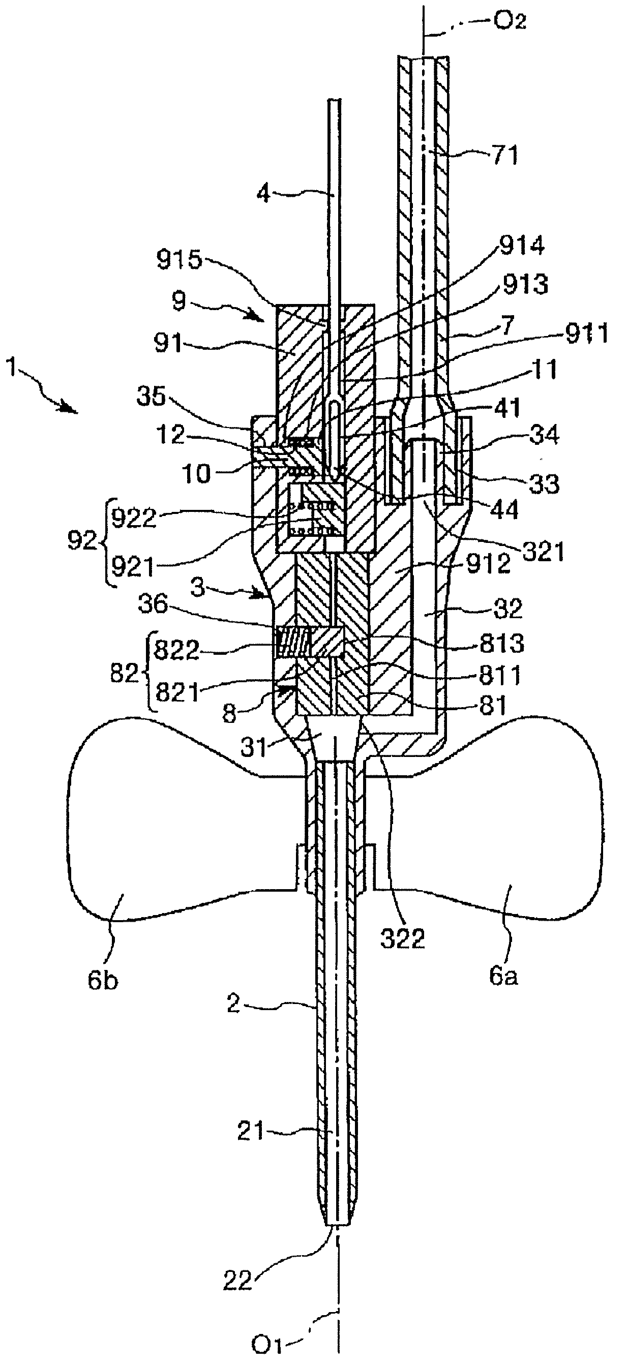
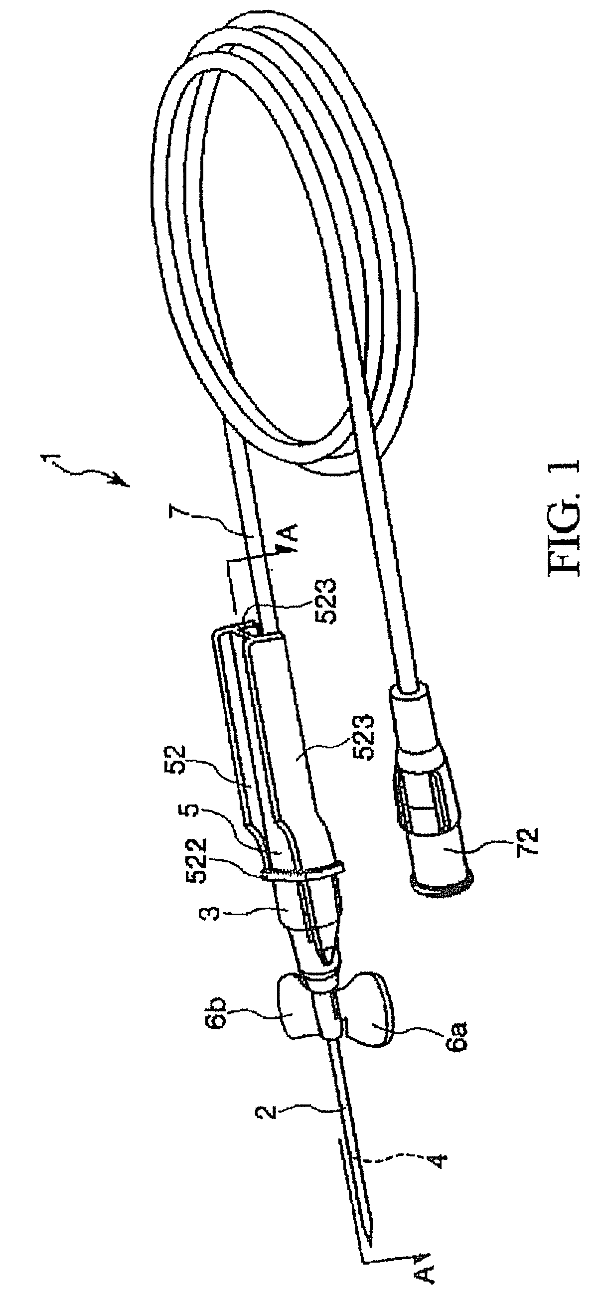
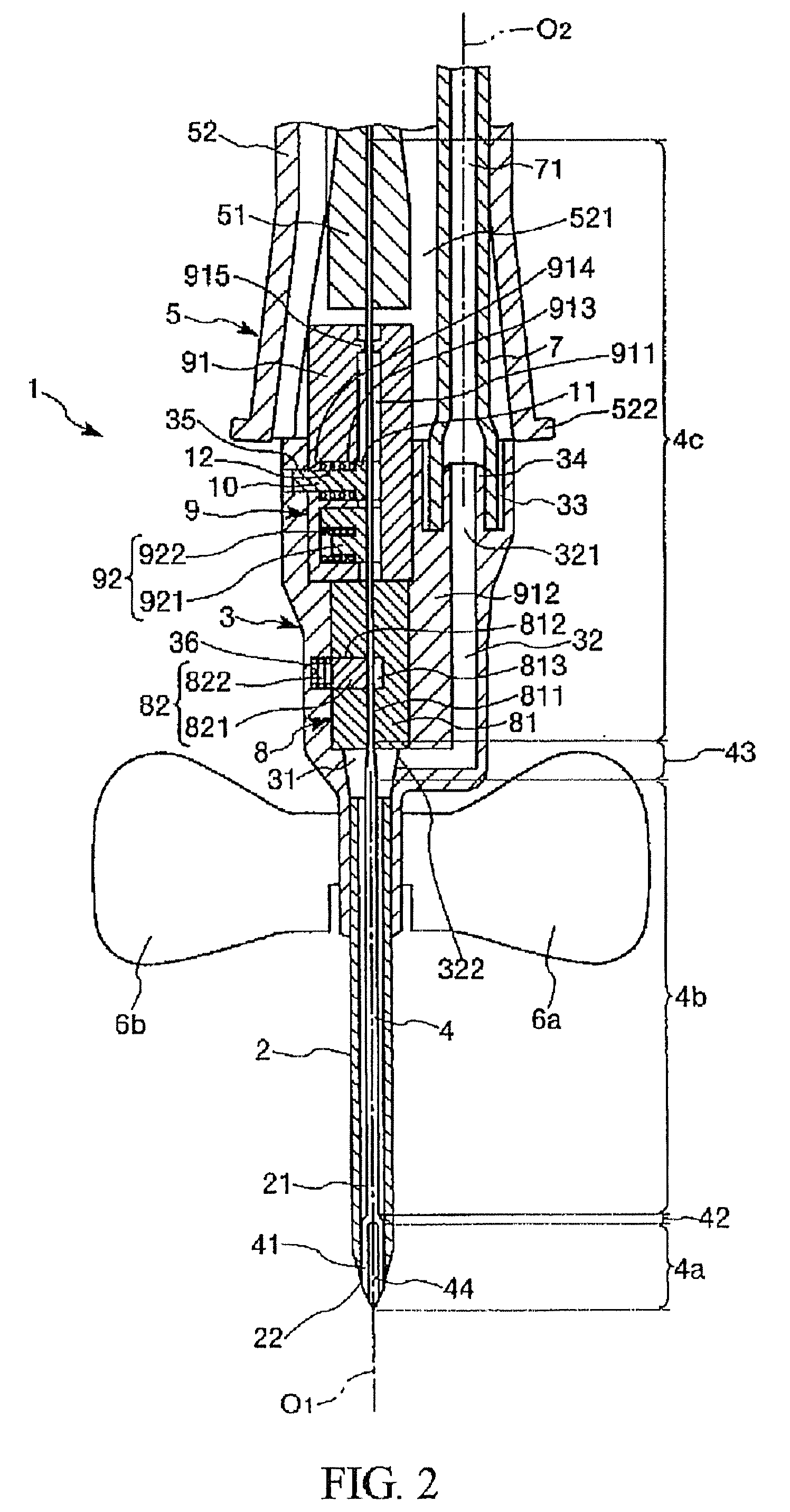
[0060]FIG. 1 is a perspective view of a first embodiment of the indwelling needle assembly according to the present invention, FIGS. 2 to 5 are sectional views taken along line A-A of FIG. 1, FIG. 6 is a perspective view, corresponding to FIG. 5, of the indwelling needle assembly shown in FIG. 1, and FIG. 7 is a perspective view of the indwelling needle assembly shown in FIG. 1, showing a condition in which a tube has been detached from an inner needle hub.

[0061]Incidentally, in the following description, the right side in FIGS. 1, 6 and 7 will be referred to as “the base end,” and the left side as “the tip.” Similarly, the upper side in FIGS. 2 to 5 will be referred to as “the base end,” and the lower side as “the tip.”

[0062]The indwelling needle assembly 1, as shown in the drawings, includes a hollow outer needle 2, an outer needle hub 3 fixed to a base end pa...

second embodiment

[0183]A second embodiment of the indwelling needle assembly according to the present invention will be described below.

[0184]FIGS. 8 and 9 are longitudinal sectional views showing, in enlarged form, a tip part of an outer needle hub, which is possessed by the indwelling needle assembly according to the second embodiment. Incidentally, in the following descriptions, the upper side in FIGS. 8 and 9 will be referred to as “the base end,” whereas the lower side will be referred to as “the tip.”

[0185]An indwelling needle assembly according to the second embodiment will now be described, while focusing on differences from the indwelling needle assembly of the aforementioned first embodiment. Descriptions of the same items that have already been mentioned above will be omitted.

[0186]The indwelling needle assembly 1 according to the second embodiment is the same as the indwelling needle assembly 1 of the aforementioned first embodiment, except for differences in the configuration of the ope...


PUM


Abstract

An indwelling needle assembly has an inner needle having a sharp point at its tip, an inner needle hub fixed to the base end of the inner needle, a hollow outer needle in which the inner needle is inserted, and a seal section provided in the outer needle hub. In the indwelling needle assembly, the seal section has open/close means having a seal section body with a hole into which the inner needle is insertable, a shutter member for opening and closing the hole, and an urging member for urging the shutter member in the direction to close the hole.

Description

TECHNICAL FIELD[0001]The present invention relates to an indwelling needle assembly, which is made to puncture a blood vessel and left dwelling within the blood vessel, in the case of an infusion, for example.BACKGROUND ART[0002]In the case that an infusion is carried out on a patient, or in other similar cases, an indwelling needle, which is connected to an infusion line, is made to puncture a blood vessel of the patient and is left dwelling within the blood vessel.[0003]Such an indwelling needle includes a hollow outer needle, an outer needle hub fixed to a base end of the outer needle, an inner needle having a sharp point at a tip portion thereof and which is inserted into the outer needle, and an inner needle hub fixed to the base end of the inner needle (refer to, for example, Patent Document 1).[0004]In the case of puncturing a patient's blood vessel with the indwelling needle, a puncturing operation is conducted in an assembled condition in which the inner needle is inserted ...

Claims


Application Information

Patent Timeline
IPC IPC(8): A61M5/32
CPCA61M5/158A61M25/0612A61M25/0618A61M2039/0673A61M39/06A61M2005/325A61M25/0637
Inventor KOBAYASHI, RYOJIOGAWA, JUNICHIMURASHITA, TAKATO
Owner TERUMO KK
Why Eureka
Try Eureka