
Shelving system

a technology of shelving system and shelving plate, which is applied in the direction of sectional furniture, adjustable height tables, dismountable cabinets, etc., can solve the problem of user performing complicated assembly operations

Inactive Publication Date: 2009-06-18
ORGANIZE IT ALL
View PDF54 Cites 42 Cited by
  • Summary
  • Abstract
  • Description
  • Claims
  • Application Information

AI Technical Summary

Benefits of technology

"The invention is a shelving unit that can be expanded vertically and horizontally. It includes vertical frames with vertical posts and shelf supports attached to the frames. The shelves have sliding mounting connectors that can slide along the vertical posts until they abut the shelf support and prevent further sliding. The sliding mounting connectors have wedge-shaped pieces to secure the shelves in place. The invention also includes a method for adding an additional shelving unit by adding a new vertical frame with vertical posts and shelf supports. The sliding mounting connectors have wedge-shaped pieces to secure the shelves in place. The technical effects of the invention include the ability to easily expand the shelving unit and secure the shelves in place."

Problems solved by technology

However, using screws to assemble the frame and shelving requires the user to perform complicated assembly operations.

Method used


Image

  • Shelving system
  • Shelving system
  • Shelving system

Examples


first embodiment

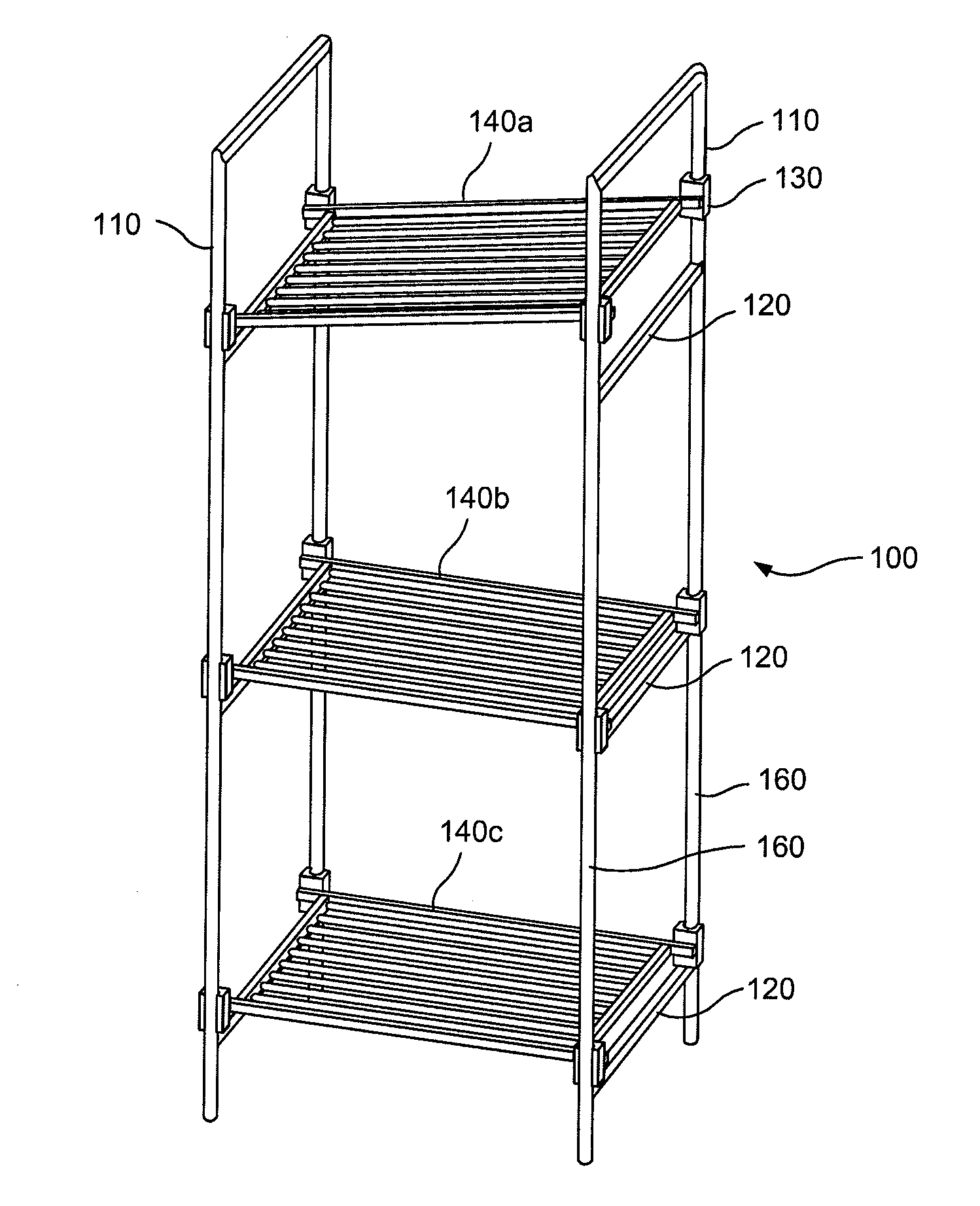
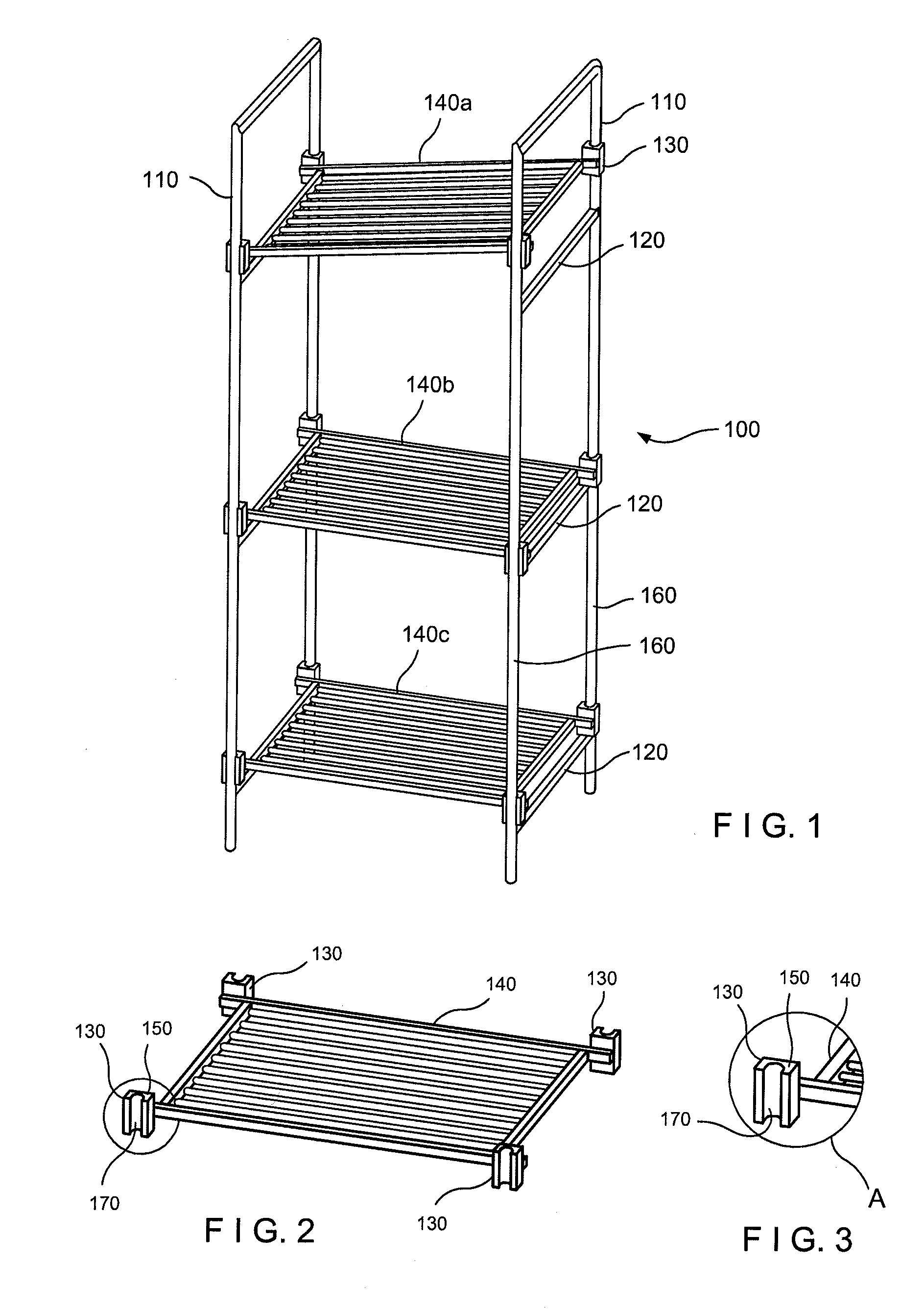
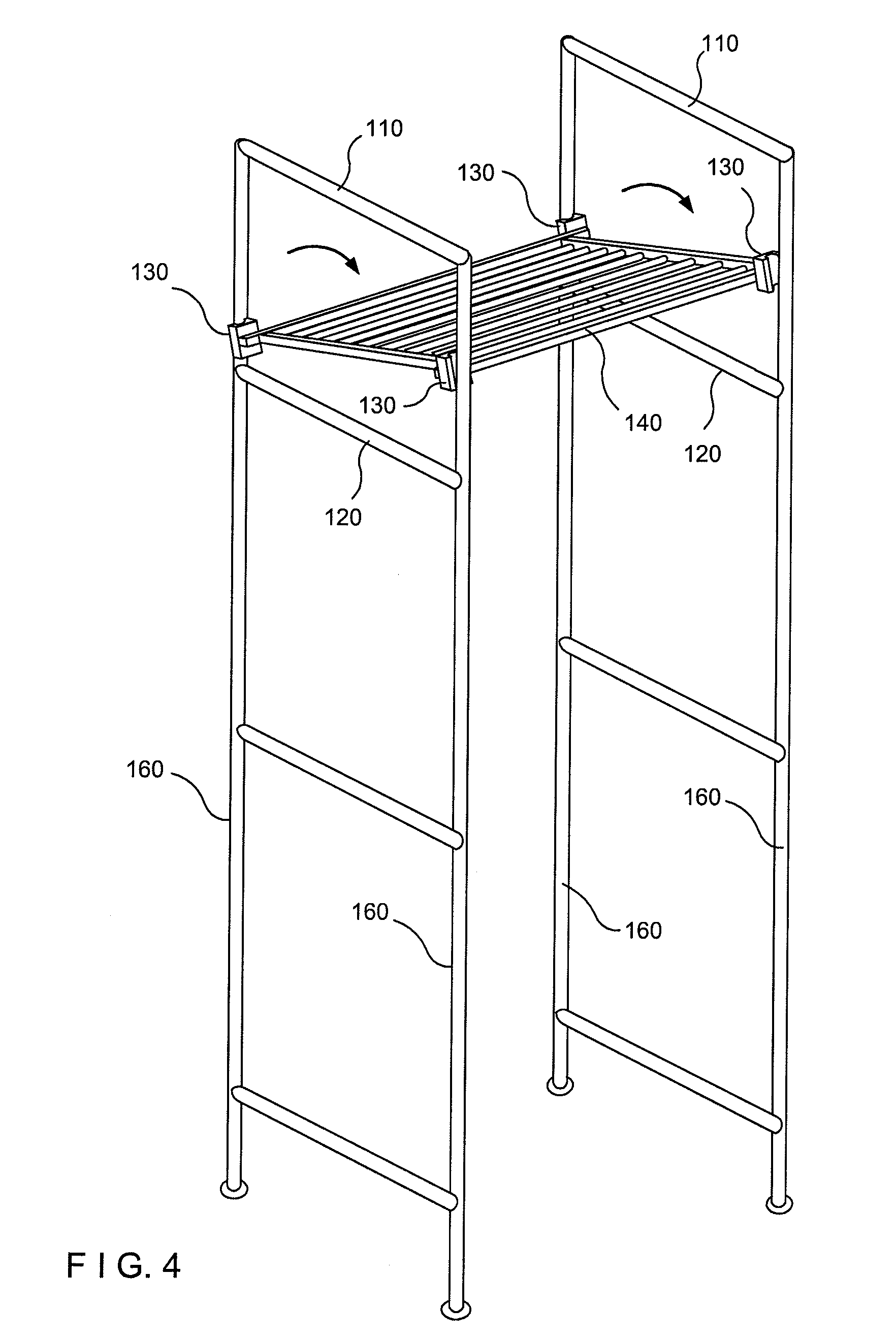
[0016]FIG. 1 illustrates a shelving unit 100 according to the present disclosure. The shelving unit can have two vertical frames 110. Vertical frames 110 can include at least two vertical posts 160 that are separated by shelf supports 120. Shelf supports 120 may be substantially horizontal, that is, perpendicular to vertical posts 110.

[0017]Shelf 140 is mounted between two vertical frames 110 using sliding mounting connectors 130 located on the periphery of the shelf. In one embodiment, the shelf 140 is a polygonal shape although the shape of the shelf can be curved or a combination of curved and straight edges. In a particular embodiment, the shelf is rectangular and the sliding mounting connectors are mounted on the shelf substantially at the corners of the shelf. Sliding mounting connectors 130 have U-shaped channels, as described below, and engage vertical post 160 of the vertical frame 110 substantially at the corners of the shelf 140.

[0018]Sliding mounting connectors 130 of a ...

second embodiment

[0025]FIG. 7 illustrates a shelving system including a shelving unit 700 that is expanded sideways. The expansion includes an additional vertical frame 710b, shelves 740b and sliding mounting connectors 730b.

[0026]Shelving unit 700 is assembled substantially as described in FIG. 1. That is, in summary, shelf 740 is assembled to vertical posts 760 of vertical frame 710a by sliding mounting connectors 730. Shelf 740 can slide along vertical posts 760 until sliding mounting connector 730 comes in contact with shelf support 720 and is supported thereby. A wedge-shaped piece (not shown) can be wedged between sliding mounting connector 730 and vertical post 760b to prevent further sliding of shelf 740.

[0027]Shelving unit 700 can be expanded sideways by assembling an additional vertical frame 710b and shelf 740b to shelving unit 700. Shelf 740b has sliding mounting connectors 730b on the periphery of the shelf 740b. In an embodiment where shelf 740b is rectangular, sliding mounting connec...


PUM

PropertyMeasurementUnit
shapeaaaaaaaaaa
heightaaaaaaaaaa
rectangular shapeaaaaaaaaaa

Abstract

A shelving system includes one or more shelving units. Each shelving unit has vertical frames each frame having at least two vertical posts. The vertical posts are separated by shelf support pieces. A shelf can be mounted horizontally between the vertical frames and be supported by the horizontal shelf support pieces. The shelf is detachably mounted to the vertical post by a sliding mounting connector having a U-shaped channel that can slide along the vertical post. A wedge-shaped piece can be wedged between the sliding mounting connector and the vertical post to secure the sliding mounting connector to the vertical post.

Description

BACKGROUND OF THE INVENTION[0001]1. Field of the Invention[0002]This invention relates generally to a shelving system. More particularly, this invention relates to a shelving system wherein the height of the shelving units can be altered, and which system can be assembled and disassembled without tools.[0003]2. Description of Related Art[0004]When assembling shelving systems, frame pieces and shelving pieces are often connected with screws to connect the shelving components. However, using screws to assemble the frame and shelving requires the user to perform complicated assembly operations. The use of screws also implies the need for tools, such as a screwdriver.SUMMARY OF THE DISCLOSURE[0005]In a first aspect of the invention, an apparatus and a method for a shelving unit includes two vertical frames each having vertical posts. One or more shelf supports attached to each vertical frame horizontally separate the respective vertical posts thereof. At least one shelf has a plurality ...

Claims


Application Information

Patent Timeline
Patent Type & Authority Applications(United States)
IPC IPC(8): A47B57/06A47B47/03A47B96/00A47B47/00
CPCA47B47/024Y10T29/49826A47B87/008A47B55/02
Inventor LEE, JAMES
Owner ORGANIZE IT ALL
Learn More