
Printer and USB device recognizing method

Inactive Publication Date: 2009-06-25
SEIKO EPSON CORP
View PDF17 Cites 8 Cited by
  • Summary
  • Abstract
  • Description
  • Claims
  • Application Information

AI Technical Summary

Benefits of technology

[0008]An advantage of some aspects of the invention is that it provides a printer wh

Problems solved by technology

However, the known USB interface is disadvantageous in that not only the initial setting of the USB interface provided in the USB device is needed to perform normal communication between the USB host and the USB device, but also a CPU, a memory, and etc. provided in the USB device must be completely initialized before the initial setting.
However, since it takes a time longer than the period in which the bus reset signal is output to perform the initialization processing, the signal line DX is likely to be pulled up as soon as the USB device is connected to the USB host while the initialization of the USB device is not completed in the above-described structure.
According to this structure, it is possible to surely establish connection to the external device even if the pulled-up signal line D+ / D− is connected USB device although the USB device is an unauthentic external device which is not adjusted to be connected to the USB host controller and initialization of the external device is not completed, because the bus reset signal is output after the initialization of the external device is completed in the standby period.

Method used


Image

  • Printer and USB device recognizing method
  • Printer and USB device recognizing method
  • Printer and USB device recognizing method

Examples


Embodiment Construction

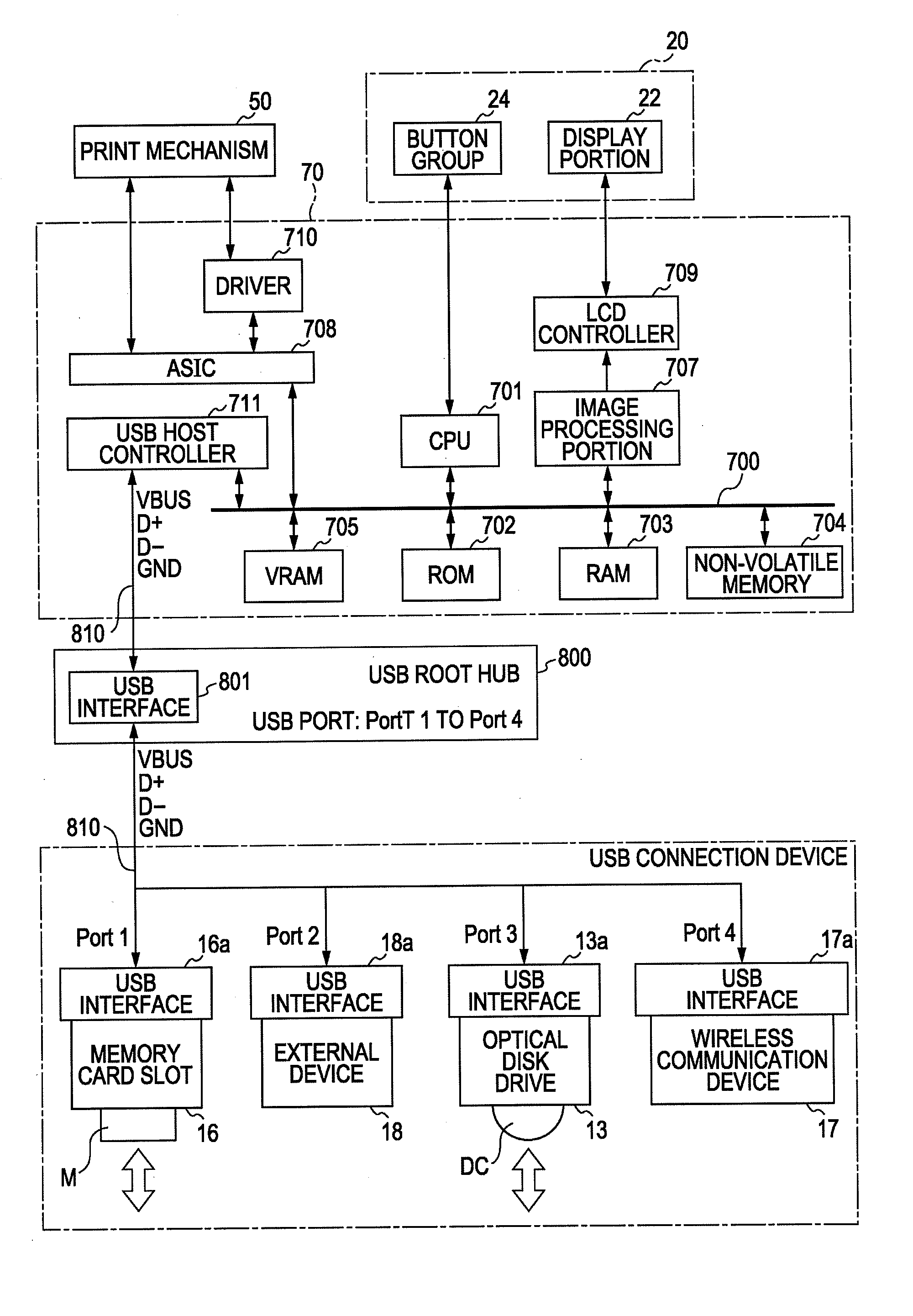
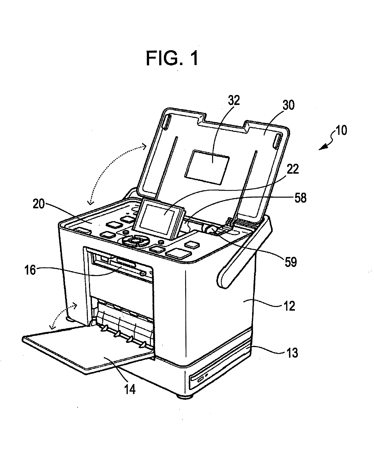
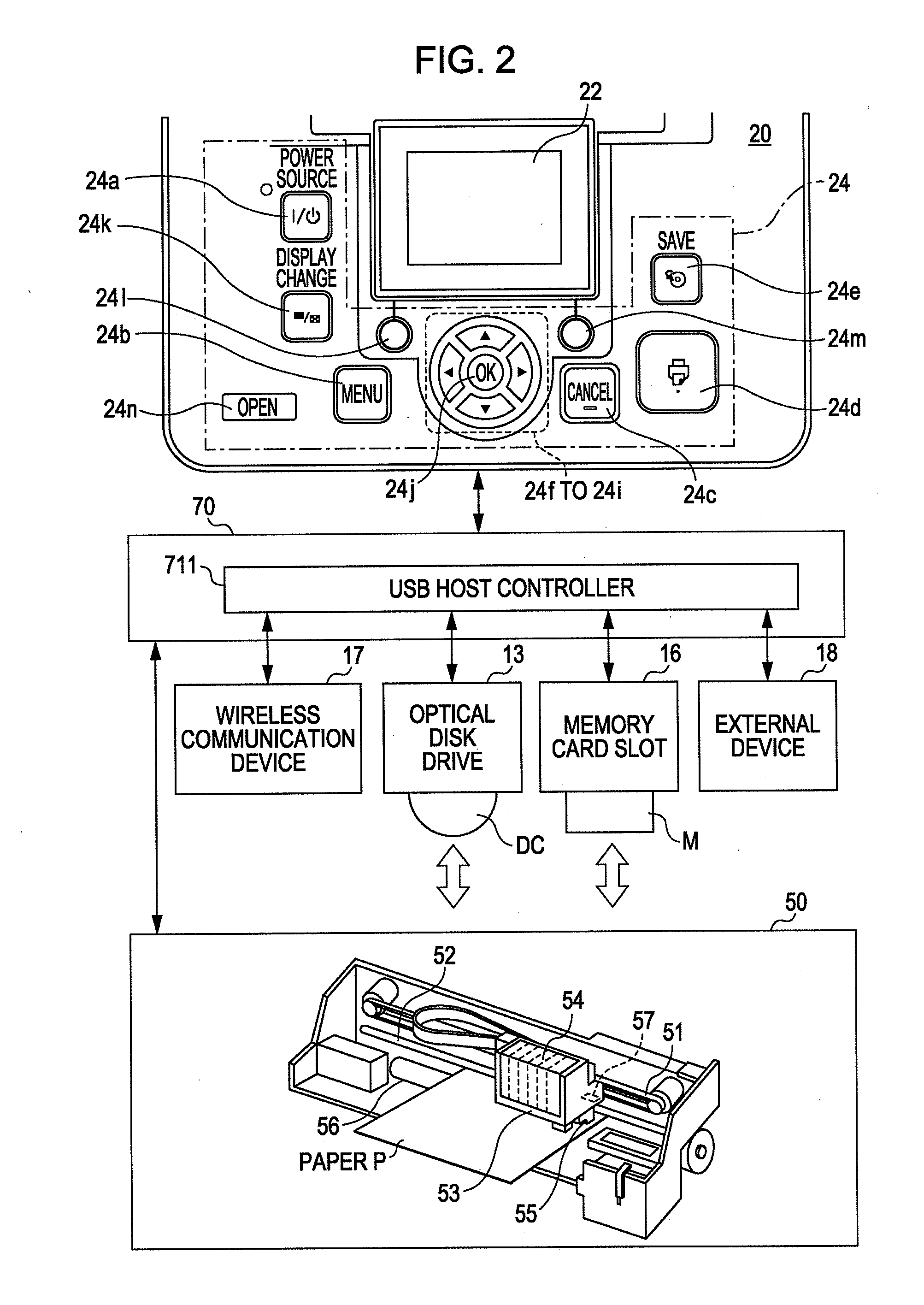
[0020]FIG. 1 is a perspective view showing a photo-printer which is a printer according to one embodiment of the invention. FIG. 2 a schematic view illustrating an inside structure of the photo-printer. In the photo-printer 10, a print mechanism 50 (see FIG. 2) is embedded inside a printer body 12 and performs printing to paper P in response to an operation command instruction from a controller 70 (see FIG. 2) which is in charge of control of the entire printer 10. The paper on which the printing is performed is discharged toward a front side of the printer body 12.

[0021]On the front face of the printer body 12, as shown in FIG. 1, a front door 14 is disposed in a freely openable manner. The front door 14 is a cover for opening and closing the front face of the printer body 12. When the front door is open, the front door serves as a paper discharge tray for receiving paper P discharged from the print mechanism 50, and a user can use various kinds of memory card slots 16 disposed on ...


PUM


Abstract

A printer includes a USB host controller and a USB root hub with a plurality of USB ports, in which the USB host controller outputs a bus reset signal to the USB device connected to a specific port when a predetermined standby time passes after a pull-up of a D+ / D− signal line of a USB device connected to at least one specific port of the plurality of USB ports is detected.

Description

CROSS-REFERENCES TO RELATED APPLICATIONS[0001]This application claims priority to Japanese Patent Application No. 2007-326866, filed Dec. 19, 2007, the disclosure of which is incorporated by reference herein.BACKGROUND[0002]1. Technical Field[0003]The present invention relates to a technique for connecting an USB device to a printer.[0004]2. Related Art[0005]JP-A-2002-202856 (paragraph 0015, FIG. 2, etc.) discloses an USB interface. The USB interface includes two signal lines D+ / D− for performing communication between an USB host and an USB device and a power supply line (VBUS) for enabling power supply to the USB device from the USB host. The USB interface is structured to enable power supply to the USB device, such as a floppy (registered trademark) disk drive (FDD) connected to the USB host such as a personal computer (PC) and a printer. The USB standard specifies that communication speed of the USB device is notified to the USB host in a manner such that when power is supplied t...

Claims


Application Information

Patent Timeline
IPC IPC(8): G06F3/00
CPCG06K15/00
Inventor NAKANO, KATSUMI
Owner SEIKO EPSON CORP
Features
  • Generate Ideas
  • Intellectual Property
  • Life Sciences
  • Materials
  • Tech Scout
  • Unparalleled Data Quality
  • Higher Quality Content
  • 60% Fewer Hallucinations
Learn More