Bi-directional, reverse blocking battery switch

Active Publication Date: 2009-07-16
GEM SERVICES
View PDF9 Cites 18 Cited by
  • Summary
  • Abstract
  • Description
  • Claims
  • Application Information

AI Technical Summary

Benefits of technology

[0010]Embodiments of the present invention relate to an improved die layout for a bi-directional and reverse blocking battery switch. According to one embodiment, two switches are oriented side-by-side (as opposed to end-to-end) in a die package. This configuration reduces the total switch resistance for a give die area, often reducing the resistance enough to avoid the use of backmetal in order to meet resistance specifications. Elimination

Problems solved by technology

This configuration reduces the total switch resistance for a give die area, often reducing th

Method used


Image

  • Bi-directional, reverse blocking battery switch
  • Bi-directional, reverse blocking battery switch
  • Bi-directional, reverse blocking battery switch

Examples


Embodiment Construction

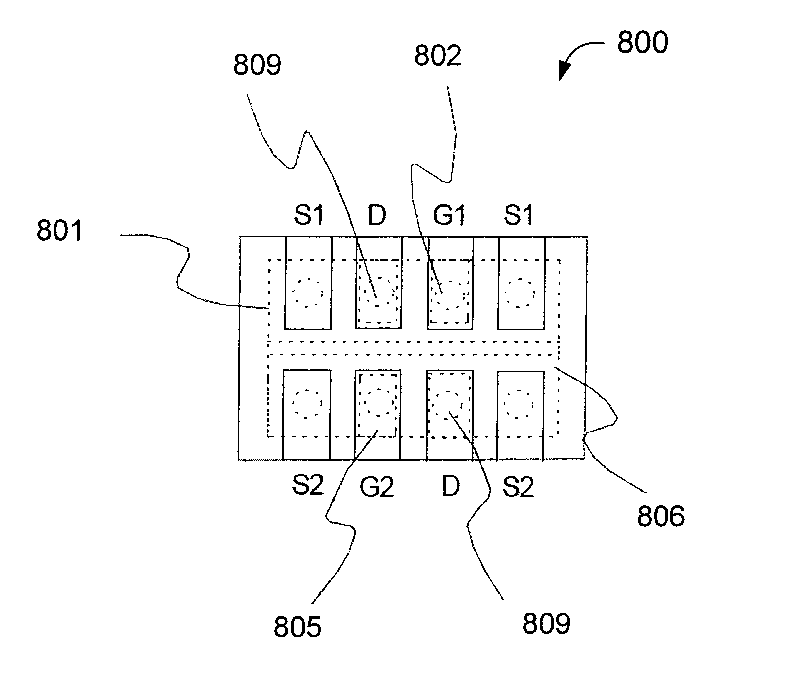
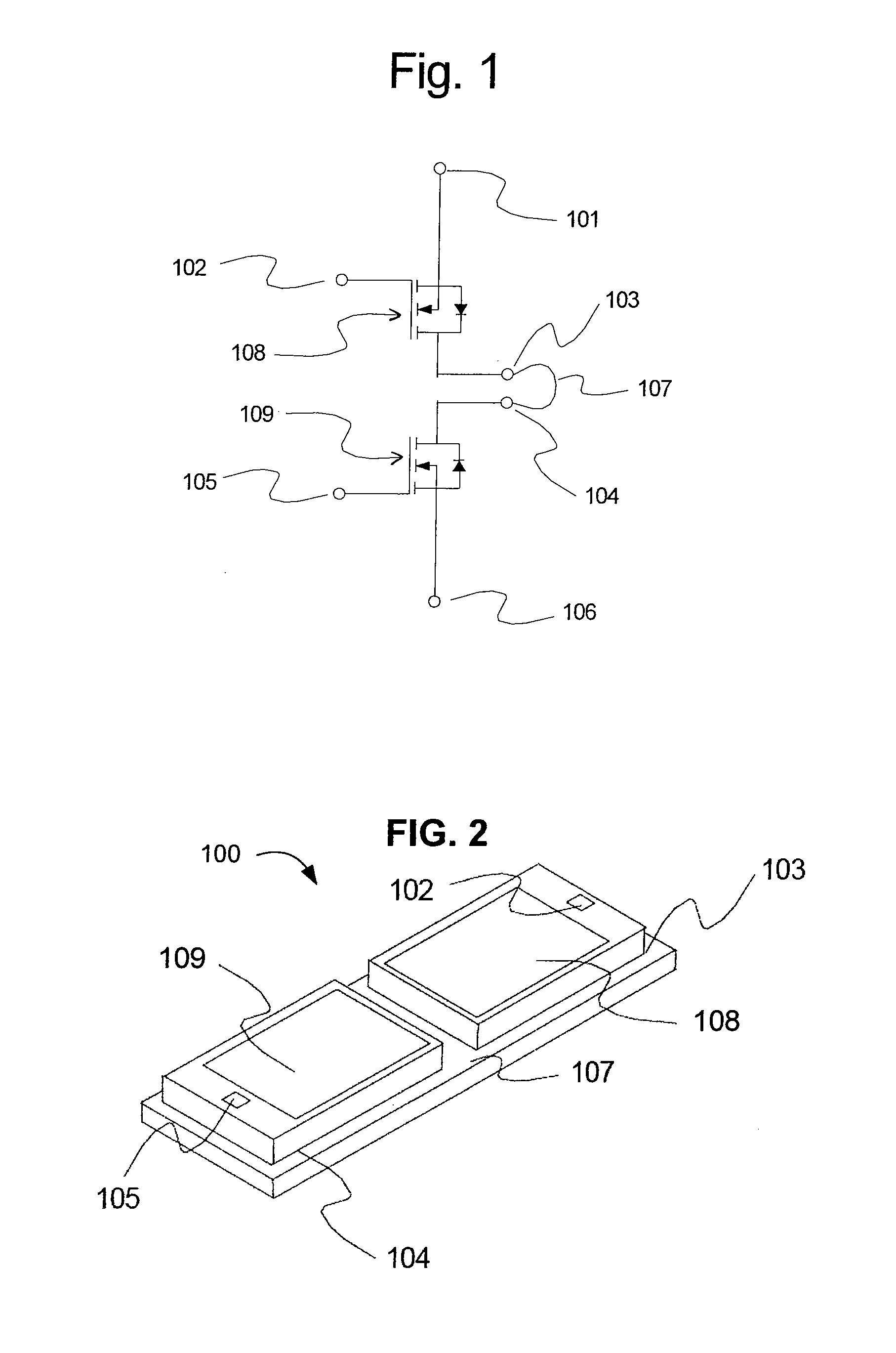
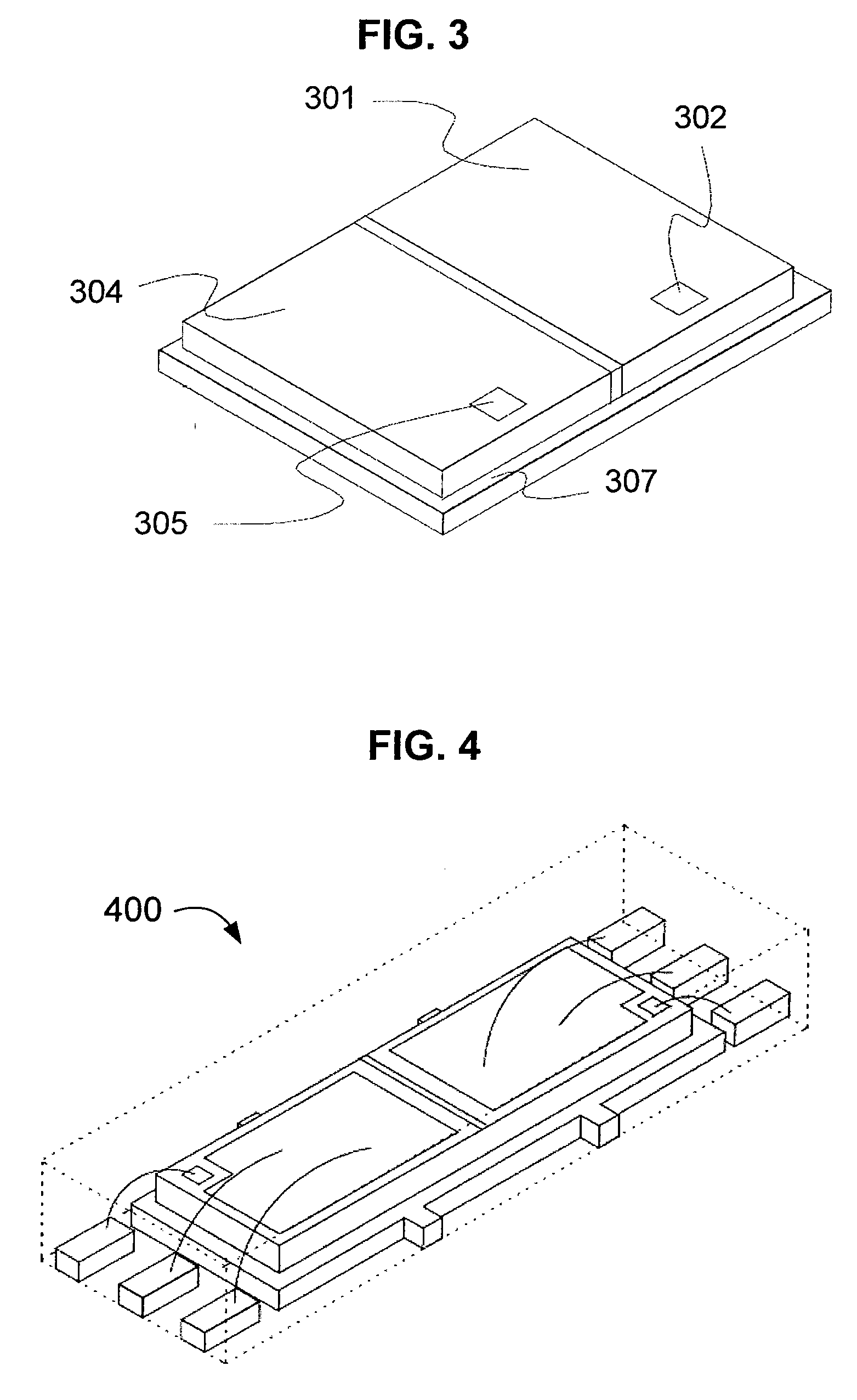
[0029]Embodiments of the present invention relate to an improved die layout for a bi-directional and reverse blocking battery switch. According to one embodiment, two switches are integrated in a common bulk Drain, side-by-side (as opposed to end-to-end) in a die package. This configuration reduces the total switch resistance, and often avoids the use of backmetal in order to meet resistance specifications. Elimination of backmetal reduces the overall cost of the die package, and removes the potential failure modes associated with the manufacture of backmetal.

[0030]Embodiments of the present invention may also allow for more pin connections and for an increased pin pitch. This results in redundant connections for higher current connections, thereby reducing the electrical and thermal resistance, and minimizing the manufacture / implementation costs of the die package. Embodiments in accordance with the present invention can also exhibit a size and form factor that fits battery cells, ...


PUM


Abstract

Embodiments of the present invention relate to an improved die layout for a bi-directional and reverse blocking battery switch. According to one embodiment, two switches are oriented side-by-side, rather than end-to-end, in a die package. This configuration reduces the total switch resistance for a given die area, often reducing the resistance enough to avoid the use of backmetal in order to meet resistance specifications. Elimination of backmetal reduces the overall cost of the die package and removes the potential failure modes associated with the manufacture of backmetal. Embodiments of the present invention may also allow for more pin connections and an increased pin pitch. This results in redundant connections for higher current connections, thereby reducing electrical and thermal resistance and minimizing the costs of manufacture or implementation of the die package.

Description

BACKGROUND OF THE INVENTION[0001]Battery life and battery size are two important features of battery powered devices. The goal of each battery charge is to perform “work”: powering functions and features that add value, with minimal loss to house-keeping and safety circuits.[0002]When potentially harmful or hazardous conditions arise, the battery may need to be disconnected. To disconnect the battery without reducing battery energy, battery disconnect switches are typically located in series with the battery.[0003]FIG. 1 shows a simplified schematic diagram of a conventional reverse blocking battery switch 100 made up of two N-channel Mosfets 108 and 109 (shown in FIG. 2). The N-channel Mosfets include source inputs 101 and 106, and gate inputs 102 and 105.[0004]The N-channel Mosfets also include respective drains 103 and 104, which are connected by jumper 107. The two Mosfets of the switch of FIG. 1 may be connected in a “common drain” configuration, utilizing an intrinsic body dio...

Claims


Application Information

Patent Timeline
IPC IPC(8): H01L27/088H01L21/56
CPCH01L2224/48091H01L2224/48247H01M10/44H02J7/0031H01L2924/3011H01L2924/13091H01L2924/00014H01L2924/00Y02E60/10H01L2224/0603
Inventor HARNDEN, JAMESCHIA, ANTHONYWONG, LIMINGYANG, HONGBOTSUI, ANTHONY C.TENG, HUIZHOU, MINGHARNDEN, LYNDA
Owner GEM SERVICES
Why Eureka
Try Eureka