Low power magnetic random access memory cell

Active Publication Date: 2012-07-19
CROCUS TECHNOLOGY
View PDF3 Cites 8 Cited by
  • Summary
  • Abstract
  • Description
  • Claims
  • Application Information

AI Technical Summary

Benefits of technology

[0033]The MRAM cell disclosed herein allows decreasing the magnitude of the spin polarized write current required to switch the magnetization direction of the storage layer by a factor of at least two compared to the one required in conventional MRAM cells, while having a magnetoresistance being about 100% or greater.
[0034]The method for forming the MRAM cell disclosed herein allows for a better control of the morphology and crystallographic structure of the deposited storage layer. For example, a small grained structure of the storage layer can be obtained such that the magnetic field required for switching the magnetization of the storage layer can be reduced compared to the storage layer of a conventional magnetic tunnel junction. Other advantages of the disclosed MRAM cell and method can be found in the detailed description below.

Problems solved by technology

However, reducing the thickness (and thus the volume) of the storage layer results in a decrease in the magnetoresistance of the magnetic tunnel junction.

Method used


Image

  • Low power magnetic random access memory cell
  • Low power magnetic random access memory cell
  • Low power magnetic random access memory cell

Examples


Embodiment Construction

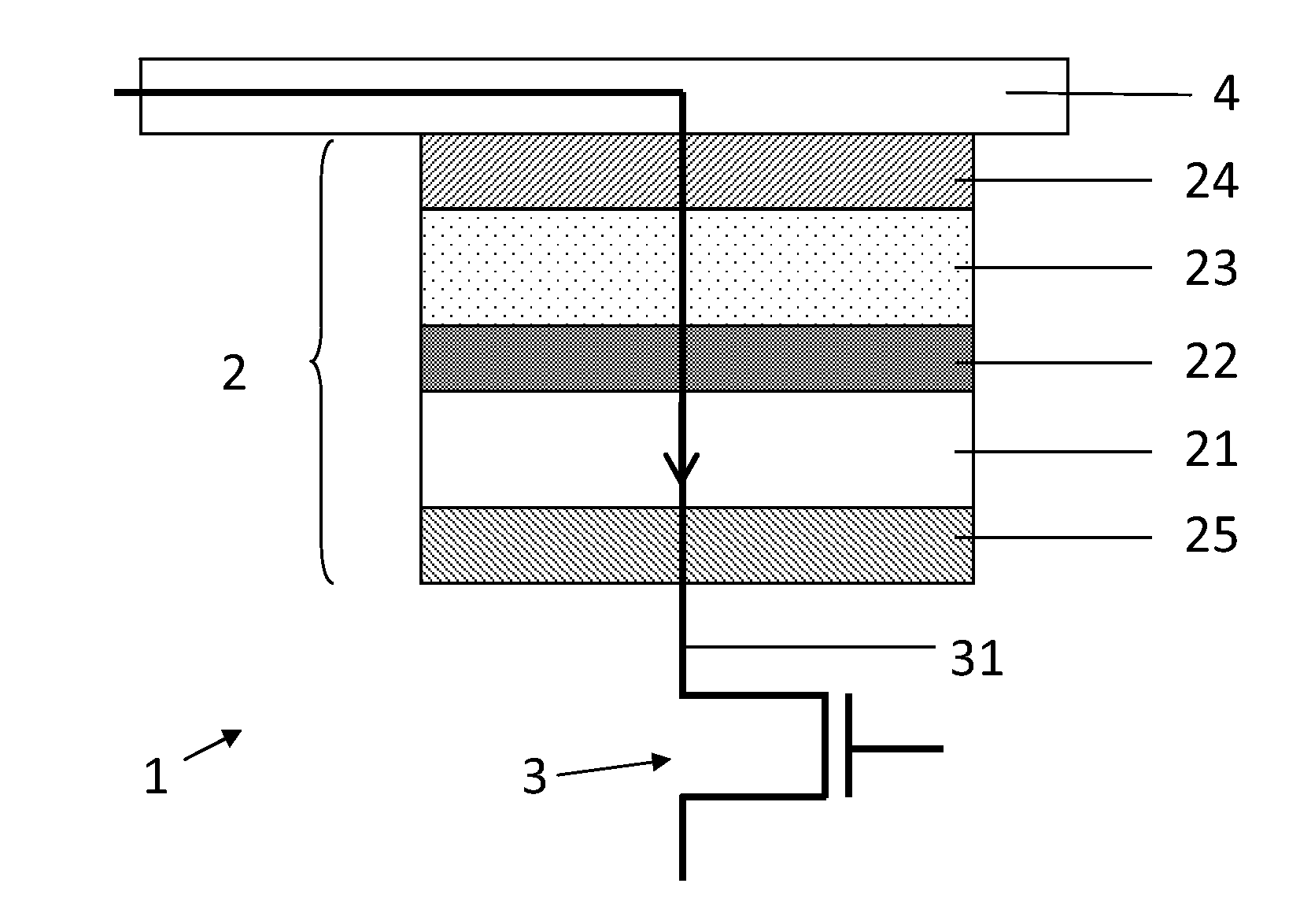
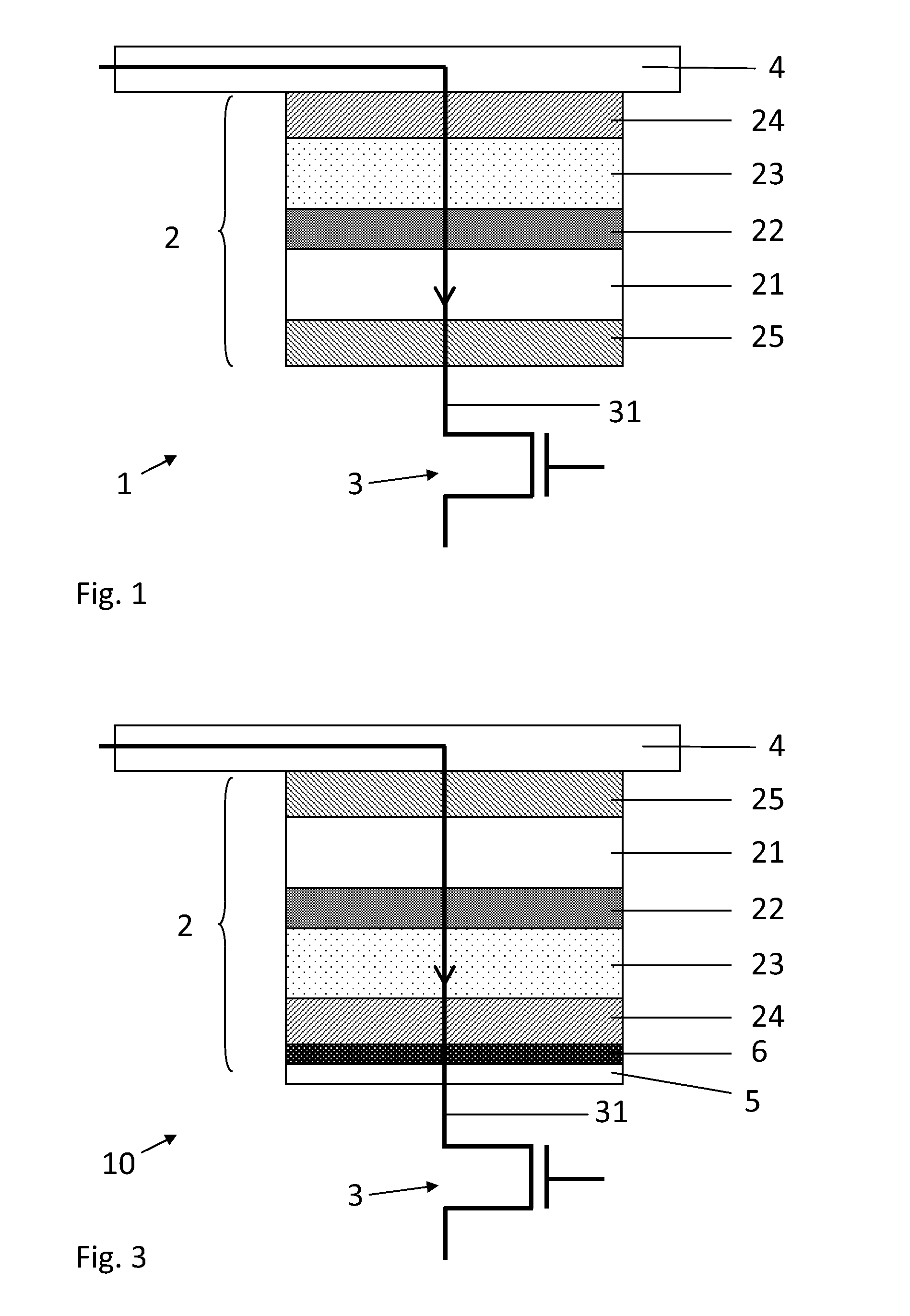
[0041]FIG. 3 represents a magnetic random access memory (MRAM) cell 10. The MRAM cell 10 comprises a magnetic tunnel junction 2 comprising, from top to bottom, a first ferromagnetic layer 21 having a first magnetization magnetization direction, a tunnel barrier layer 22, and a second ferromagnetic layer 23 having a second magnetization direction that can be adjusted with respect to the first magnetization direction. A top electrode, or current line 4, is electrically connected to the magnetic tunnel junction 2 on the side of the first ferromagnetic layer 21. A front-end layer comprising, represented by a CMOS selection transistor 3 in FIG. 3 is electrically connected to the magnetic tunnel junction 2, possibly via a bottom electrode 5, on the side of the second ferromagnetic layer 23. The front-end layer can comprise one or more layers of a dielectric such as silicon oxide or low-k dielectric materials disposed over silicon single-crystal silicon, for example. The front-end layer ma...


PUM


Abstract

The present disclosure concerns a magnetic random access memory (MRAM) cell suitable for performing a thermally assisted write operation or a spin torque transfer (STT) based write operation, comprising a magnetic tunnel junction comprising a top electrode; a tunnel barrier layer comprised between a first ferromagnetic layer having a first magnetization direction, and a second ferromagnetic layer having a second magnetization direction adjustable with respect to the first magnetization direction; a front-end layer; and a magnetic or metallic layer on which the second ferromagnetic layer is deposited; the second ferromagnetic layer being comprised between the front-end layer and the tunnel barrier layer and having a thickness comprised between about 0.5 nm and about 2 nm, such that magnetic tunnel junction has a magnetoresistance larger than about 100%. The MRAM cell disclosed herein has lower power consumption compared to conventional MRAM cells.

Description

FIELD OF THE INVENTION[0001]The present invention concerns a magnetic random access memory (MRAM) cell suitable for performing a thermally assisted write operation or a spin torque transfer (STT) based write operation, and that can be written with a small field or spin polarized write current while having a high magnetoresistance.DESCRIPTION OF RELATED ART[0002]Magnetic tunnel junction (MTJ) based magnetic random access memory (MRAM) cells have been the object of a renewed interest with the discovery of magnetic tunnel junctions having a strong magnetoresistance at ambient temperature. Indeed, these MRAM cells have many advantages such as speed (a write and a read operation can has duration of a few nanoseconds), non volatility, and insensitivity to ionizing radiations. Consequently, they are increasingly replacing memories using more conventional technology, for example, based on the charge state of a capacitor, such as DRAM, SRAM and FLASH.[0003]In their simplest implementation, M...

Claims


Application Information

Patent Timeline
IPC IPC(8): H01L29/82H01L43/08
CPCG11C11/1675G11C11/161G11C11/15
Inventor DUCRUET, CLARISSEPORTEMONT, CÉLINEPREJBEANU, IOAN LUCIAN
Owner CROCUS TECHNOLOGY
Why Eureka
Try Eureka