Starter with compact structure

a technology of starting device and compact structure, which is applied in the direction of engine starters, machines/engines, relays, etc., can solve the problems of increasing the installation space of engine starting device and difficult to avoid interference with other installed components, and achieve the effect of minimizing a dimensional limitation

Active Publication Date: 2009-07-23
DENSO CORP
View PDF12 Cites 47 Cited by
  • Summary
  • Abstract
  • Description
  • Claims
  • Application Information

AI Technical Summary

Benefits of technology

[0011]The present invention has been completed with a view to addressing the above issues and has an object to provide a starter which includes an electromagnetic switch, operative to open or close a main contact of a motor circuit, and a solenoid, having a function to push a pinion gear toward an engine, which can minimize a dimensional limitation.

Problems solved by technology

This results in a remarkable disadvantage with an increased installation space in dimension of the engine.
With the starter disclosed in Patent Publication 1, however, the motor carries thereon the electromagnetic switch and the electromagnetic force means in areas parallel to each other and, hence, it is considered that it is often difficult to avoid the interference with the other installed component part in the two directions on the radial direction.

Method used


Image

  • Starter with compact structure
  • Starter with compact structure
  • Starter with compact structure

Examples


embodiment

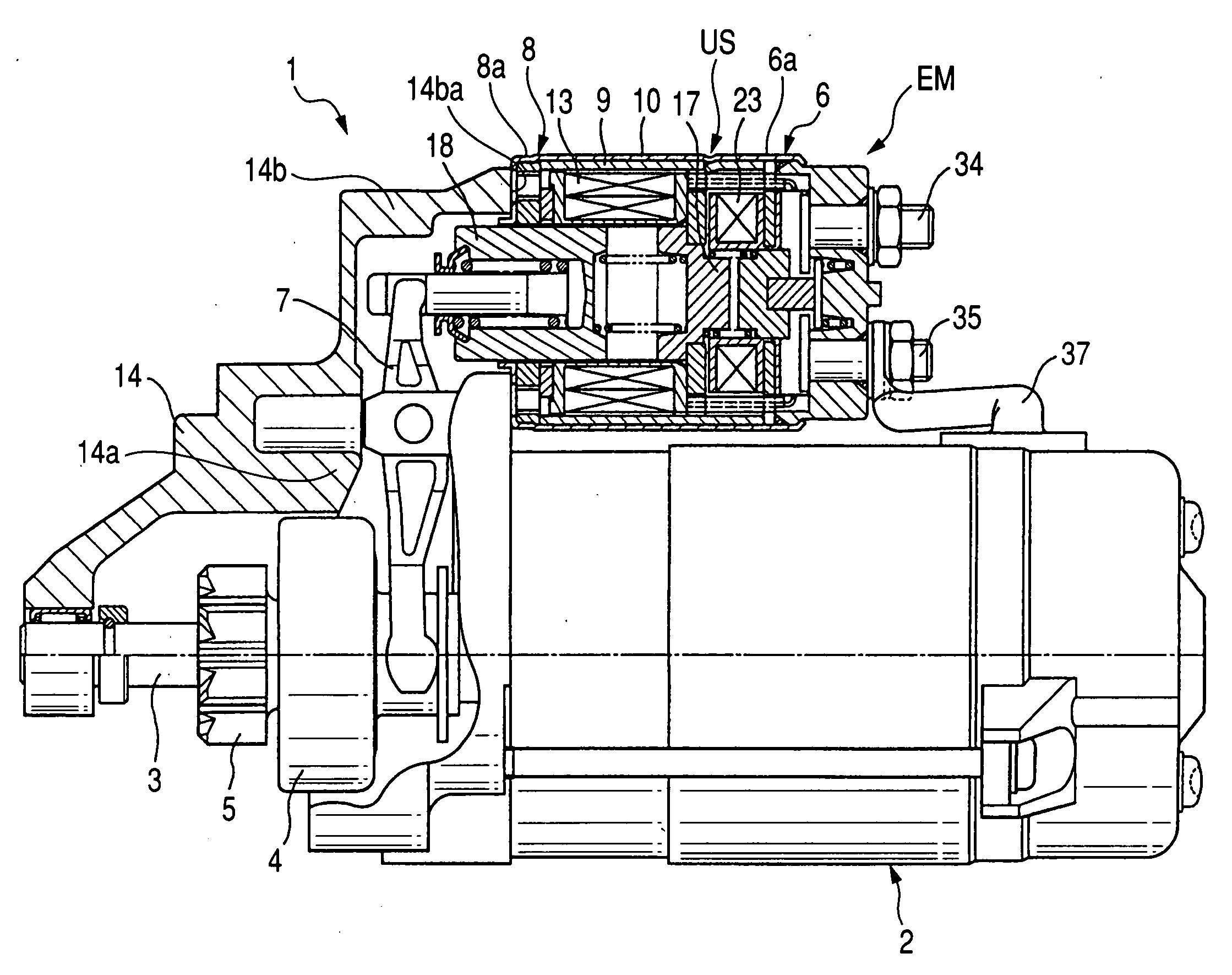
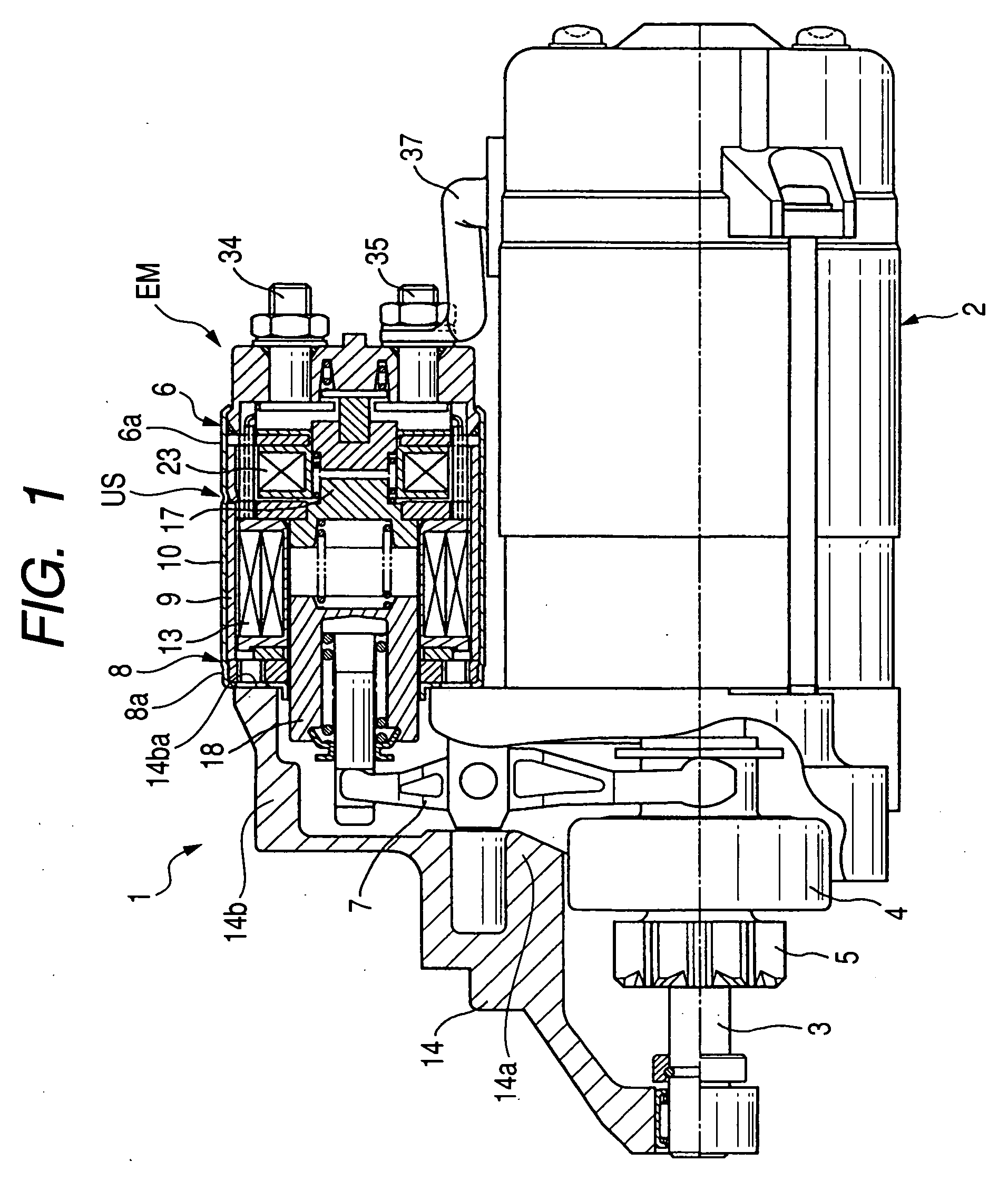
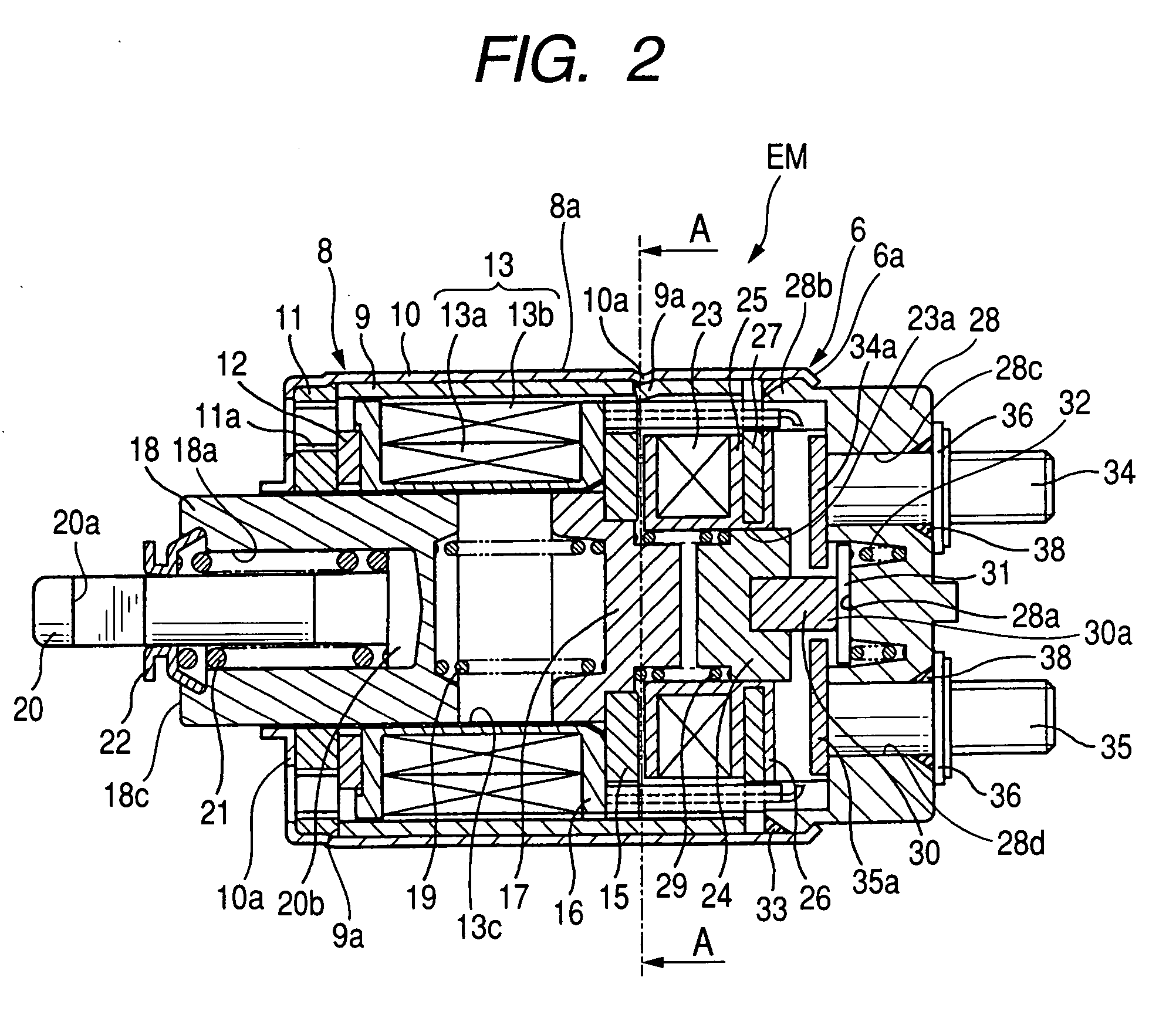
[0045]FIG. 1 is an overall structural view showing the starter of the present embodiment implementing the present invention. FIG. 2 is a cross-sectional view of an electromagnetic switch and a solenoid installed on the starter 1.

[0046]As shown in FIG. 1, the starter 1 includes a motor 2 having an armature 2a (see FIG. 7) for generating a rotational force, an output shaft 3 rotatably driven with the motor 2, a pinion gear 5 slidably disposed on the output shaft 3 to be movable unitarily with a clutch 4, an electromagnetic switch 6 operative to open or close a main contact (described below) provided in an energization circuit (hereinafter referred to as “a motor circuit”), and a solenoid 8 having a function to push the pinion gear 5 via a shift lever 7 in a position (leftward as viewed in FIG. 1) opposite to the motor 2. The starter 1 further includes a starter housing 14 having a first mounting area 14a, on which the motor 2 is axially mounted, and a second mounting area 14b on which...


PUM


Abstract

An electromagnetic switch is disclosed as having an electromagnetic switch, operative to open or close a main contact of a motor circuit, and a solenoid having a function to push a pinion gear to a position away from a motor. The electromagnetic switch and the solenoid are placed in series in a unitary structure such that the electromagnetic switch and the solenoid have a switch case and a solenoid case both of which are integrally formed with each other to be contiguous in an axial direction.Further, a stationary core for the electromagnet and a stationary core for the solenoid are integrally formed and an operational direction of a plunger for the electromagnet and an operational direction of a plunger for the solenoid are set to be opposite in direction.

Description

CROSS REFERENCE TO RELATED APPLICATIONS[0001]This application is based on Japanese Patent Application Nos. 2008-9004 and 2008-314622, filed on Jan. 18, 2008 and Dec. 10, 2008, respectively, the contents of which are hereby incorporated by reference.BACKGROUND OF THE INVENTION[0002]1. Technical Field of the Invention[0003]The present invention relates to starters and, more particularly, to a starter having an electromagnetic switch, operative to open or close a main contact of a motor circuit, and a solenoid for pushing a pinion gear toward a ring gear of an engine.[0004]2. Description of the Related Art[0005]In the related art, there has been known an engine starter device of a structure disclosed in Utility Model Publication No. 56-42437 (Patent Publication 1). With such a structure, the engine starter device is comprised of an electromagnetic switch operative to open or close a main contact of a motor circuit, electromagnetic force means (an electromagnet device) having a function...

Claims


Application Information

Patent Timeline
Patent Type & Authority Applications(United States)
IPC IPC(8): F02N15/06
CPCF02N15/022Y10T74/131F02N2011/0892F02N15/067Y10T74/132Y10T74/137F02N11/087H01H51/065H02K7/14F02N15/06F02N15/02F02N11/00
Inventor NIIMI, MASAMI
Owner DENSO CORP
Why Eureka
Try Eureka