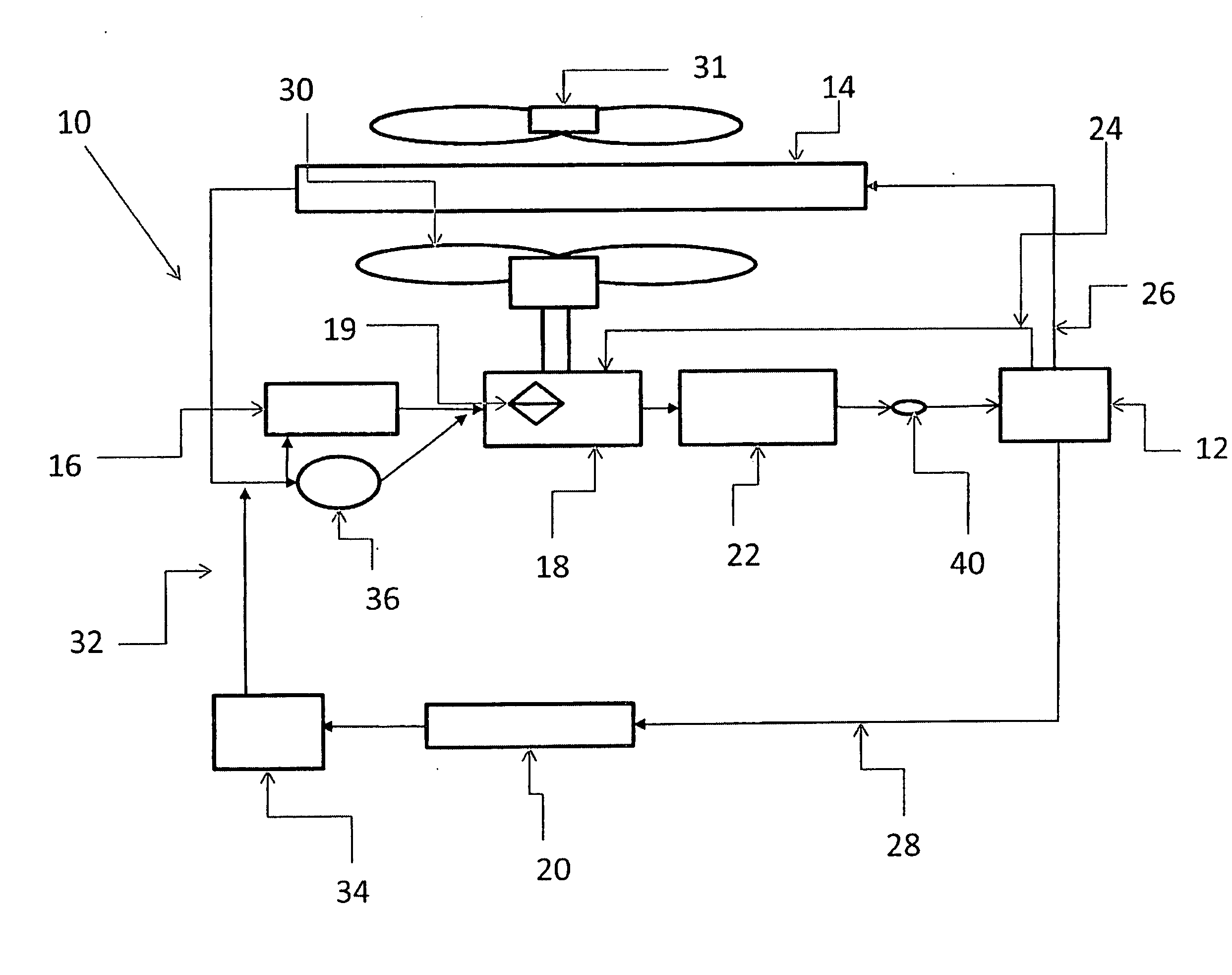
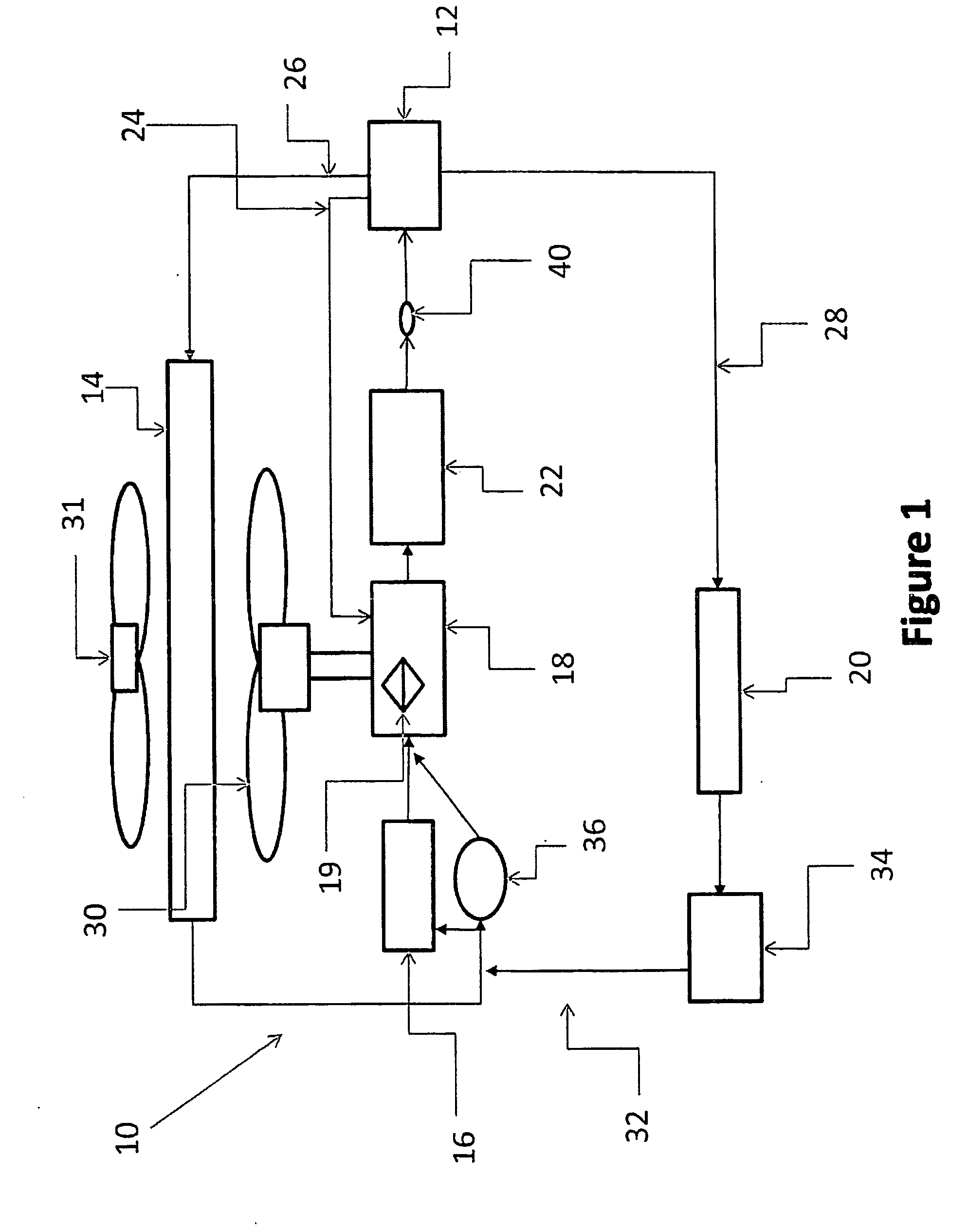
[0006]The present system comprises an electric pump and a mechanical pump to pump coolant through the cooling system of an
internal combustion engine, thus minimizing the parasitic loss of the system and improving the total
fuel efficiency of the vehicle. The electric pump and mechanical pump may operate in tandem, or separately, as required to meet engine
heat rejection requirements. A
clutch is operatively engaged to the mechanical pump and is designed to engage and disengage the mechanical pump. When the
clutch is in the off position, the mechanical pump is disengaged from the system. When the system requires, the clutch is switched to the on position, thereby engaging the mechanical pump. Depending upon the position of the clutch, at least one pump is in operation when the internal
combustion engine is operating, unless during initial start-up. If the heater control valve is in the open position, as selectively operated by the user in the passenger compartment for the specific purpose of providing heat to the passenger compartment, the coolant flows through the
heater core, whereby the heat is removed from the coolant, and the coolant is recirculated through the system.
[0007]The
thermostat controls the flow of the coolant to the radiator by gradually allowing passage of coolant at a predetermined
coolant temperature. When the coolant is cold, the thermostat prevents the flow of the coolant to the radiator until the coolant reaches the required predetermined temperature, necessitating the need for the heat to be removed from the engine by the coolant through the introduction of the coolant to the radiator. The radiator acts as a
heat exchanger, whereby the coolant flows through the radiator, releasing heat to the air flowing therethrough, so that the coolant can be recirculated to the engine to absorb more heat, and repeat the process.
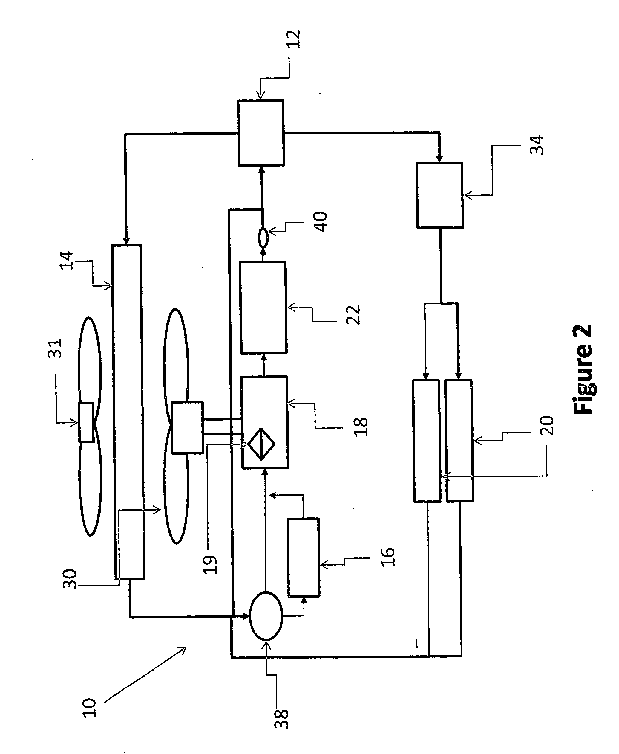
[0008]The electric pump is intended to provide low engine load
coolant flow of the coolant through the cooling system, while the mechanical pump is intended to provide a high engine load
coolant flow. In one embodiment, the mechanical pump is fitted with an electric clutch that operatively disconnects the pump
impeller and, optional, pump mounting
mechanical fan when only low engine load coolant flow, provided by the electric pump, is desired. Advantageously, the use of only the electric pump decreases the parasitic loss as compared to conventional belt driven pump systems. The use of the electric clutch to engage and disengage the pump
impeller and, optional, pump mounting
mechanical fan, eliminates the high parasitic loss associated with the use of these
mechanical devices during typical operation of the internal combustion engine.
[0009]In an exemplary embodiment of the present invention, a cooling system for an internal combustion engine having a rotating member and using coolant in a
liquid cooling system is provided, including a radiator for dissipating the heat from the coolant, an electric pump for pumping the coolant through the cooling system, a mechanical pump operatively connected to the rotating member for pumping coolant through the cooling system, and a clutch for engaging and disengaging the second pump at a predetermined interval, thus minimizing the parasitic loss of the system by improving total fuel economy of the vehicle.
[0015]In yet another exemplary embodiment of the present invention, a cooling system for an internal combustion engine of a motor vehicle having a rotating member and using a coolant in a
liquid cooling system is provided, including a radiator for dissipating the heat from the coolant, an electric fan that transfers air through the radiator for transferring the heat from the coolant to the air, an electric pump for pumping the coolant through the cooling system, a mechanical pump in series with the electric pump, wherein the mechanical pump is rotatably engaged to the rotating member for pumping the coolant through the cooling system, and a clutch for engaging and disengaging the mechanical pump at a predetermined interval, thus minimizing parasitic loss of the system by improving total fuel economy of the vehicle.
[0019]In yet another exemplary embodiment of the present invention, a cooling system for an internal combustion engine of a motor vehicle having a rotating member and using a coolant in a liquid cooling system is provided, including a radiator for dissipating the heat from the coolant, a mechanical fan that draws air through the radiator for transferring the heat from the coolant to the air; an electric fan that transfers air through the radiator for transferring the heat from the coolant to the air; an electric pump for pumping coolant through the cooling system, a mechanical pump in series with the electric pump, wherein the mechanical pump is rotatably engaged to the rotating member that drives the mechanical pump and pumps coolant through the cooling system, and a clutch for engaging and disengaging the mechanical pump and engaging and disengaging a mechanical fan, thus minimizing the parasitic loss of the system by improving total
fuel efficiency of the vehicle, and a three way valve for directing the flow of coolant through the cooling system.

