Apparatus and method for beamforming in a multi-antenna system

a multi-antenna system and apparatus technology, applied in the field of multi-antenna system, can solve the problems of pilot overhead increase, decrease in throughput, and increase in feedforward channel capacity proportional to the number of receive ends, and achieve the effect of maximizing the sum ra

Inactive Publication Date: 2009-08-06
SAMSUNG ELECTRONICS CO LTD
View PDF3 Cites 96 Cited by
  • Summary
  • Abstract
  • Description
  • Claims
  • Application Information

AI Technical Summary

Benefits of technology

This patent describes an apparatus that helps improve communication between multiple antennas by focusing transmissions towards specific receivers. It uses a method called beamforming which involves confirming the channels of different receivers, selecting optimal codes from a pre-existing set of options, generating new weights based on these selections, and then applying those weights to individual signals before sending them out. These techniques can help increase data throughput and make wireless networks more efficient.

Problems solved by technology

This patent discusses how to improve performance in wireless networks with multiple antennas. One challenge is finding efficient ways to use available frequencies when providing multimedia services to many users. Another issue is minimizing interference between users who are served by different antennas. Dedicated pilots and feedback channels may help alleviate these issues but come with their own limitations such as increased pilot overhead or reduced throughput.

Method used


Image

  • Apparatus and method for beamforming in a multi-antenna system
  • Apparatus and method for beamforming in a multi-antenna system
  • Apparatus and method for beamforming in a multi-antenna system

Examples


Embodiment Construction

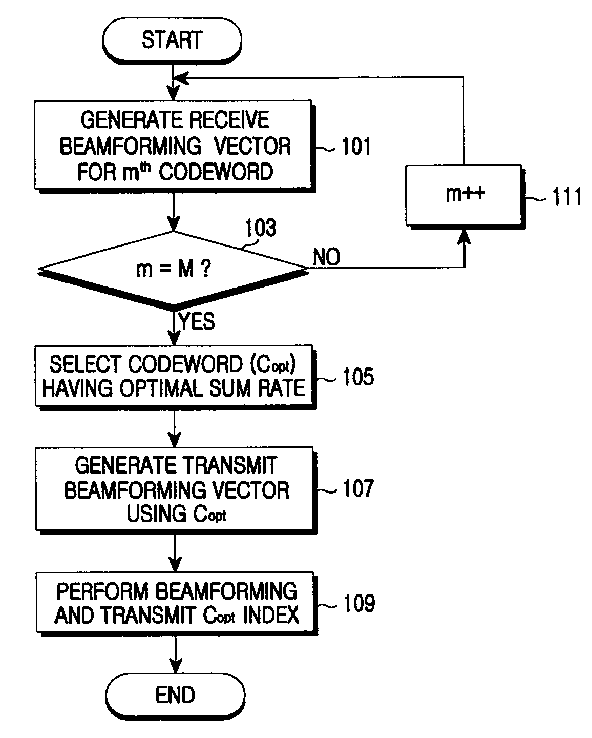
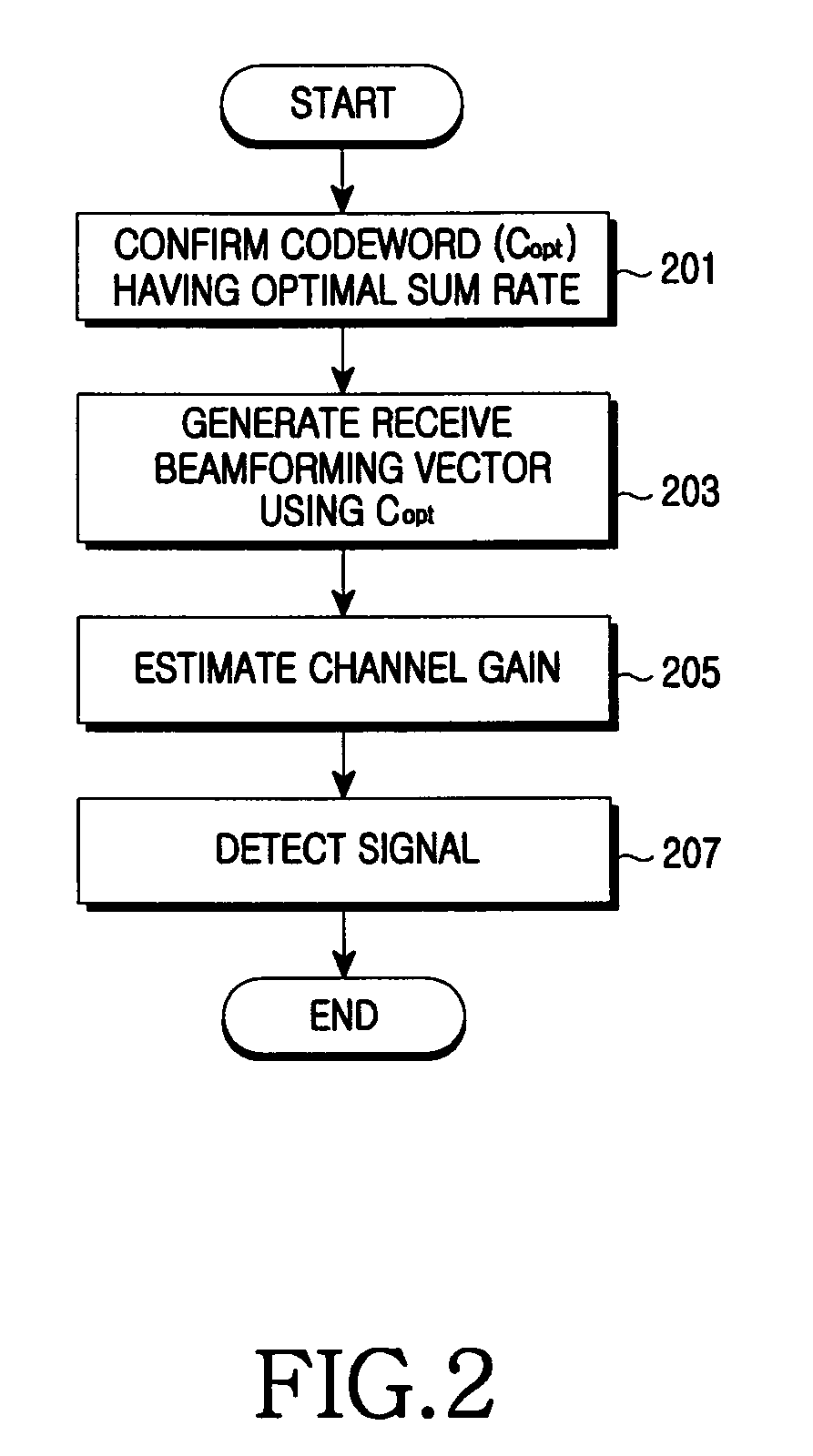
[0025]FIGS. 1 through 4, discussed below, and the various embodiments used to describe the principles of the present disclosure in this patent document are by way of illustration only and should not be construed in any way to limit the scope of the disclosure. Those skilled in the art will understand that the principles of the present disclosure may be implemented in any suitably arranged wireless communication network.

[0026]A technology for generating a preceding weight and post-processing weight for coordinated beamforming based on a codebook in a multi-antenna system of a multiple user environment according to an exemplary embodiment of the present invention is described below.

[0027]In the following description, the precoding weight is called a transmit beamforming weight, and the post-processing weight is called a receive beamforming weight.

[0028]It is assumed that a transmit end is aware of downlink channel information of receive ends located in a service area. However, the sam...


PUM


Abstract

An apparatus and method for beamforming in a multi-antenna system are provided. The method includes assuming at least one codeword comprised in a codebook as a precoding weight of a reference receive end and generating post-processing weights of at least two receive ends, confirming a codeword maximizing a sum rate using the post-processing weights, generating preceding weights of the receive ends using the codeword maximizing the sum rate, and precoding a transmit signal using the generated precoding weights and transmitting the precoded transmit signal to each receive end.

Description


Claims


Application Information

Patent Timeline
Owner SAMSUNG ELECTRONICS CO LTD
Why Eureka
Try Eureka