
OMAMRC transmission method and system with slow link adaptation

a transmission method and link adaptation technology, applied in the field of digital communication, can solve the problems and the subject of slow fading and gaussian white noise of links between the different nodes of the system

Active Publication Date: 2022-08-16
ORANGE SA (FR)
View PDF5 Cites 0 Cited by
  • Summary
  • Abstract
  • Description
  • Claims
  • Application Information

AI Technical Summary

Benefits of technology

[0021]The method is such that the link adaptation is of slow type and consists in maximizing the sum-rate of all the sources subject to the constraint of a target average BLER (prediction based on the probability of outage) εcom after X≥1 cooperative transmissions.
[0031]Thus, contrary to the known and widely used techniques, the link adaptation is of slow type and not fast and takes account of a number X of retransmissions. A fast adaptation is based on an instantaneous knowledge of the quality of the channel. According to the invention, the slow adaptation has the advantage of limiting the in-band and out-band occupancy of the control information necessary to this adaptation. The invention also comprises X cooperative retransmissions which makes it possible to take account of the quality of the source-relay and relay-destination links in the choice of the initial rate per source.
[0032]According to well-known and widely deployed techniques linked with the LTE (3GPP) standard, the initial value of the MCS is determined to be the greatest possible subject to the constraint of a block error rate BLER that is individual (for each source) which does not exceed εind=10% by considering that the BLER is averaged relative to the noise. The residual BLER (10%) is, according to these techniques, taken into account in retransmissions which take place after the first transmissions. The BLER according to the LTE is a trade-off between a minimization of the control signals and a maximization of the radio rate from the very first transmissions. The radio rate for the source i is given by Ri*(1−BLERi) with Ri being the rate and BLERi being the individual block error rate for a given propagation channel.
[0037]According to one embodiment, the method is such that, after maximization, the M individual rates taken together are increased or reduced simultaneously.
[0042]According to one embodiment, the method is such that, for any selection of IR-HARQ type, the destination selects the node which maximizes the number of sources decoded correctly after retransmission by this node, the number of sources decoded correctly being derived from a prediction by the destination.

Problems solved by technology

The links between the different nodes are subject to slow fadings and to Gaussian white noise.
The links between the different nodes of the system are subject to slow fadings and to Gaussian white noise.

Method used


Image

  • OMAMRC transmission method and system with slow link adaptation

Examples


first embodiment

[0179]A first embodiment considers a common ACK / NACK message and a selection of a relay node based on the mutual item of information.

[0180]According to this embodiment, only one subset is considered in the equation (6). This subset is that which comprises all the sources of the set of the sources not correctly decoded by the destination, i.e. ′=d,t−1. Thus, at the start of the round t, the destination chooses the cooperative node at E at∈∪ which maximizes.

[0181]a^t=⁢{∑s∈𝒮_d,t-1⁢⁢Is,d+∑l=1t-1⁢⁢α⁢⁢Ia^l,d⁢1{𝒮_d,t-1⋂𝒮^al,l-1≠ϕ}+α⁢⁢Iat,d⁢1{𝒮_d,t-1⋂𝒮at,t-1≠ϕ}}=⁢{Iat,d⁢1{𝒮_d,t-1⋂𝒮at,t-1≠ϕ}}(11)

[0182]Given that the choice of at does not influence the first two terms of the right hand part of the inequality (7), then the problem of maximization can be transformed into a maximization of the third term:

[0183]α⁢⁢Iat,d⁢1{𝒰⋂𝒮at,t-1≠ϕ}.

Such a choice of ′ amounts to performing a selection of the node with the item of information Iat,d that is the greatest out of all the nodes which are ca...

second embodiment

[0184]A second embodiment considers a common ACK / NACK message and a selection of a relay node based on the product of mutual information and on the cardinality of the decoding set.

[0185]According to this embodiment, the selection concerns the node with the greatest product Iat,d×|ad,t−1|. The product is a good joint indicator of the mutual item of information Iad, d and of the cardinality of the decoding set |at,t−1|.

third embodiment

[0186]A third embodiment considers a common ACK / NACK message and a selection of a relay node based on a prediction of the decoded sources.

[0187]According to this embodiment, on each round, the destination sequentially examines the sources from s1 to sM and then the relays from r1 to rL. For each node at out of these nodes and on condition that d,t−1∩ad,t−1≠Ø the destination tries to determine how many more sources it could decode of the preceding round if this node were selected.

[0188]To this end, for each of these nodes at, the destination checks for each source si∈d,t−1 whether the individual outage event Os,t(at, at,t−1) after the round t is true or not. Next, the destination counts the number of the individual outage events equal to zero (i.e. false) to obtain the number of sources that can be newly correctly decoded. The destination then chooses the node at which leads to the greatest number of newly decoded sources. If several nodes lead to the same number, the destination cho...


PUM


Abstract

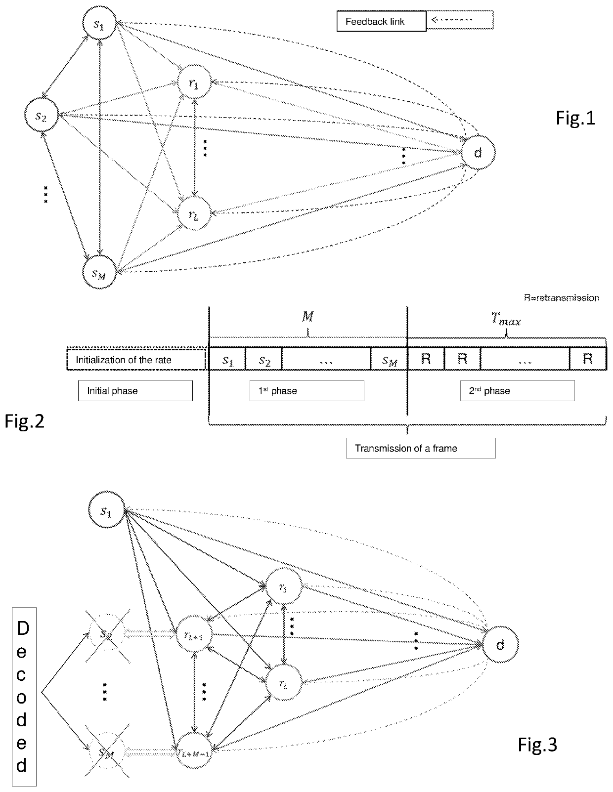
A method for transmitting successive messages forming a frame in a telecommunication system with M sources (s1, . . . , sM), L relays and a destination, M>1, L≥1 according to an orthogonal multiple-access scheme of the channel between the M sources and the L relays with a maximum number of M+Tmax time slots per transmitted frame including M slots and Tmax cooperative transmission slots. The method includes: a slow type link adaptation determining an initial rate for each source by destination based on an average SNR of each link and transmitting to each source the initial rate; and for each frame out of several, successively transmitting the messages of the M sources during the M slots phase with, respectively, modulation and coding schemes determined from the initial rates. The link adaptation maximizes the aggregate rate of all the sources subject to the constraint of a target average BLER εcom after Tmax≥X≥1 cooperative transmissions.

Description

CROSS-REFERENCE TO RELATED APPLICATIONS[0001]This Application is a Section 371 National Stage Application of International Application No. PCT / FR2018 / 000162, filed Jun. 6, 2018, the content of which is incorporated herein by reference in its entirety, and published as WO 2018 / 229362 on Dec. 20, 2018, not in English.FIELD OF THE DISCLOSURE[0002]The present invention relates to the field of digital communications. In this field, the invention relates more particularly to the transmission of coded data between sources and a destination with relaying by relays, the relayed communications are said to be cooperative. In the context of the invention, a source can serve as relay after the decoding of the information received from another source. The systems considered comprise multiple sources, one or more relays (a relay possibly being a source) and a destination.[0003]There are numerous relaying techniques known as: “amplify and forward”, “decode and forward”, “compress-and-forward”, “non...

Claims


Application Information

Patent Timeline
Patent Type & Authority Patents(United States)
IPC IPC(8): H04B7/155H04L1/00H04L1/18H04L1/20H04L5/16H04W72/04H04W72/08
CPCH04B7/15542H04L1/0003H04L1/0009H04L1/1864H04L1/203H04L5/16H04W72/0446H04W72/082H04L1/0019H04L1/1812H04L2001/0097H04W72/541
Inventor CEROVIC, STEFANMOHAMAD, ABDULAZIZVISOZ, RAPHAEL
Owner ORANGE SA (FR)
Learn More