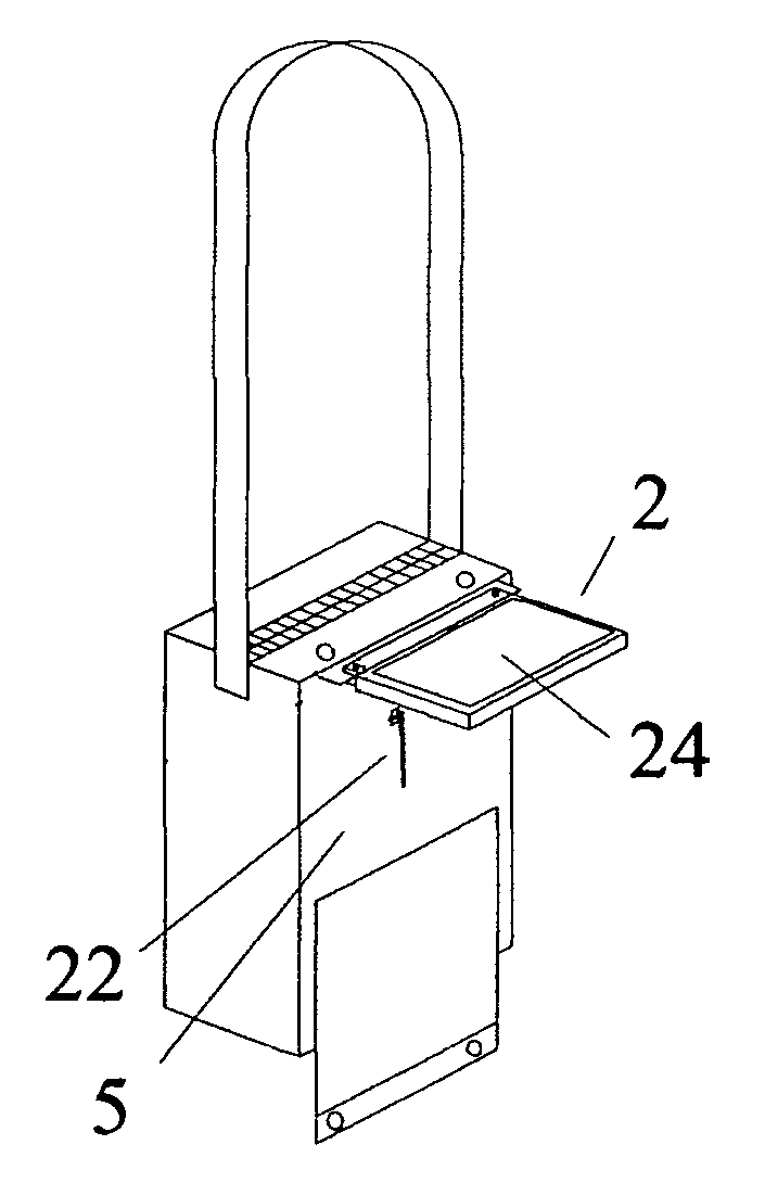
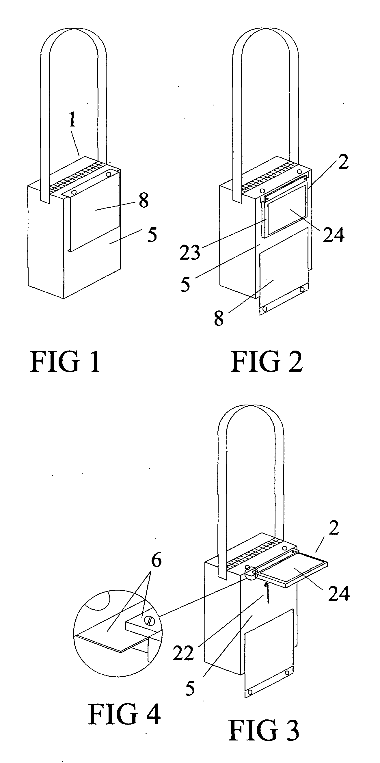
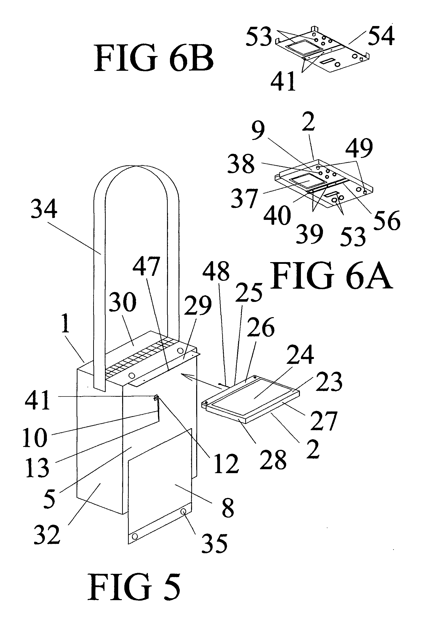
Bag computer display panel prop assembly

a technology for computer display panels and props, which is applied in the field of bag computer display panel prop assemblies, can solve the problems that other simpler pcems, such as flexible fabric mounting attachments, may not be able to do, and achieve the effect of simple, inexpensive, light and replaceable propping

Inactive Publication Date: 2009-08-13
DALEY III CHARLES A
View PDF29 Cites 46 Cited by
  • Summary
  • Abstract
  • Description
  • Claims
  • Application Information

AI Technical Summary

Problems solved by technology

Although the pivoting computer equipment mounts (PCEM), which pivotally hold the display panel to the bag, may be able to hold any angle of the display panel relative to the bag front, other simpler PCEMs, for example a flexible fabric mounting attachment, may not be able to do so.

Method used


Image

  • Bag computer display panel prop assembly
  • Bag computer display panel prop assembly
  • Bag computer display panel prop assembly

Examples


second embodiment

[0139]In a second embodiment, shown in profile view FIGS. 22A, 22B, 22C, 22D, 22E and front view 22F, the bag 1 computer, in various positions for operation, is shown with the display panel held to the bag with a pivoting computer equipment mount (PCEM) 6 and the display panel prop assembly is between the bag front and display panel back. The prop bar 10 is made of a semi rigid material and has a fitting to match a pivoting prop holder 44 at one end 12. The remainder of the prop bar is designed to pass through a complimentary “sliding prop holder”42 which, because of friction or ratcheting between the prop bar and sliding prop holder, can hold the bar at any distance from its connection with the pivoting prop holder. The position of the sliding prop holder on the prop bar decides the display panel angle relative to the bag front. The sliding prop holder 42 may have the form of a channel, track, slot or cylinder parallel to the display panel 2 back side or bag front 5, depending wher...

third embodiment

[0142]In the display panel prop assembly, shown in profile views FIGS. 23A, 23B, 23C, 23D, 23E and front view 23F, the bag 1 computer, in various positions for operation, is shown with the display panel held to the bag with a pivoting computer equipment mount (PCEM) 6 and the display panel prop assembly is between the bag front and display panel back. The prop bar 10 is rigid and has a pivoting prop holder permanently fixed to one end. The pivoting prop holder would normally be comprised of an axle / bearing hinge 19 and includes a friction, spring or ratchet mechanism which can maintain the angle between the bag front and prop bar with enough force to support the display panel 2. The pivoting prop holder is attached to the bag 1 front wall 5 or display panel back side and may include a flange 21 to aid attachment and to stabilize the prop holder.

[0143]The prop bar end 12 not attached to the pivoting prop holder is designed to pass through or rub against a sliding prop holder 42 and a...


PUM


Abstract

Disclosed is an assembly to hold the angular position of a display panel relative to the bag front to which it is pivotally attached. The display panel is attached to the bag so it can pivot flat against the bag front or away from the bag into the line of sight of the computer operator / bag wearer. The display back and bag front have holders meant to match the ends of a prop bar which extends between the two. There are three embodiments; 1) a rigid bar between the two holders, 2) a semi-rigid bar held pivotally with the first holder and the opposite bar end sliding through the second holder with friction to hold the display panel position, 3) a rigid bar held pivotally with a first holder having a hinge with friction to hold the display panel position and the opposite bar end sliding along the second holder.

Description

CROSS-REFERENCE TO RELATED APPLICATIONS[0001]This application is a Continuation-In-Part and claims the filing benefit under 35 U.S.C. § 120 of pending U.S. application Ser. No. 11 / 796,920, filed May 1, 2007 and is incorporated herein by reference.[0002]This application claims the filing benefit under 35 U.S.C. §119(e) of U.S. Provisional Application No. 61 / 125,861, filed on Apr. 30, 2008, the entire teachings of which are incorporated herein by reference.TECHNICAL FIELD[0003]The present invention relates to a computer designed for mobile use.BACKGROUND OF THE INVENTION[0004]Bag computers are composed of a bag and computer joined so that the display panel pivots around the top front end of the bag so it can lay approximately flat against the bag front when stored or pivot with its display facing outward into the line of sight of the operators when in use. There may be a keyboard lower down on the bag front and there may be manual controls on the back of the display panel.[0005]The co...

Claims


Application Information

Patent Timeline
Patent Type & Authority Applications(United States)
IPC IPC(8): G06F1/16
CPCG06F1/1628
Inventor DALEY, III, CHARLES A.
Owner DALEY III CHARLES A
Why Eureka
Try Eureka