Expandable vertebral device with cam lock

a technology of expanding vertebrae and cam locks, which is applied in the field of supporting adjacent vertebrae, can solve problems such as back pain, leg pain, or other neurological disorders, and achieve the effect of improving the stability and stability of the devi

Inactive Publication Date: 2009-08-13
K2M
View PDF21 Cites 95 Cited by
  • Summary
  • Abstract
  • Description
  • Claims
  • Application Information

AI Technical Summary

Problems solved by technology

However, when the vertebrae are misaligned or a constriction is formed in the spinal cana...

Method used


Image

  • Expandable vertebral device with cam lock
  • Expandable vertebral device with cam lock
  • Expandable vertebral device with cam lock

Examples


Embodiment Construction

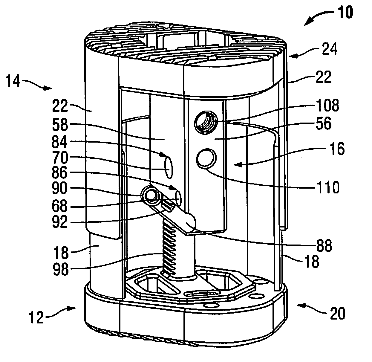
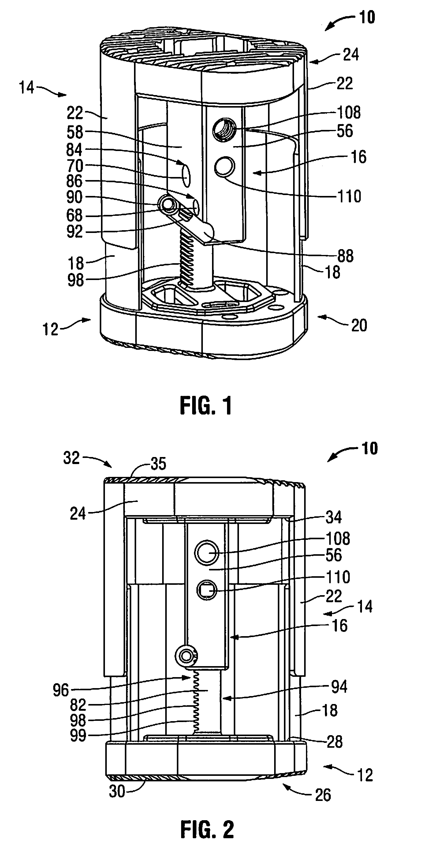
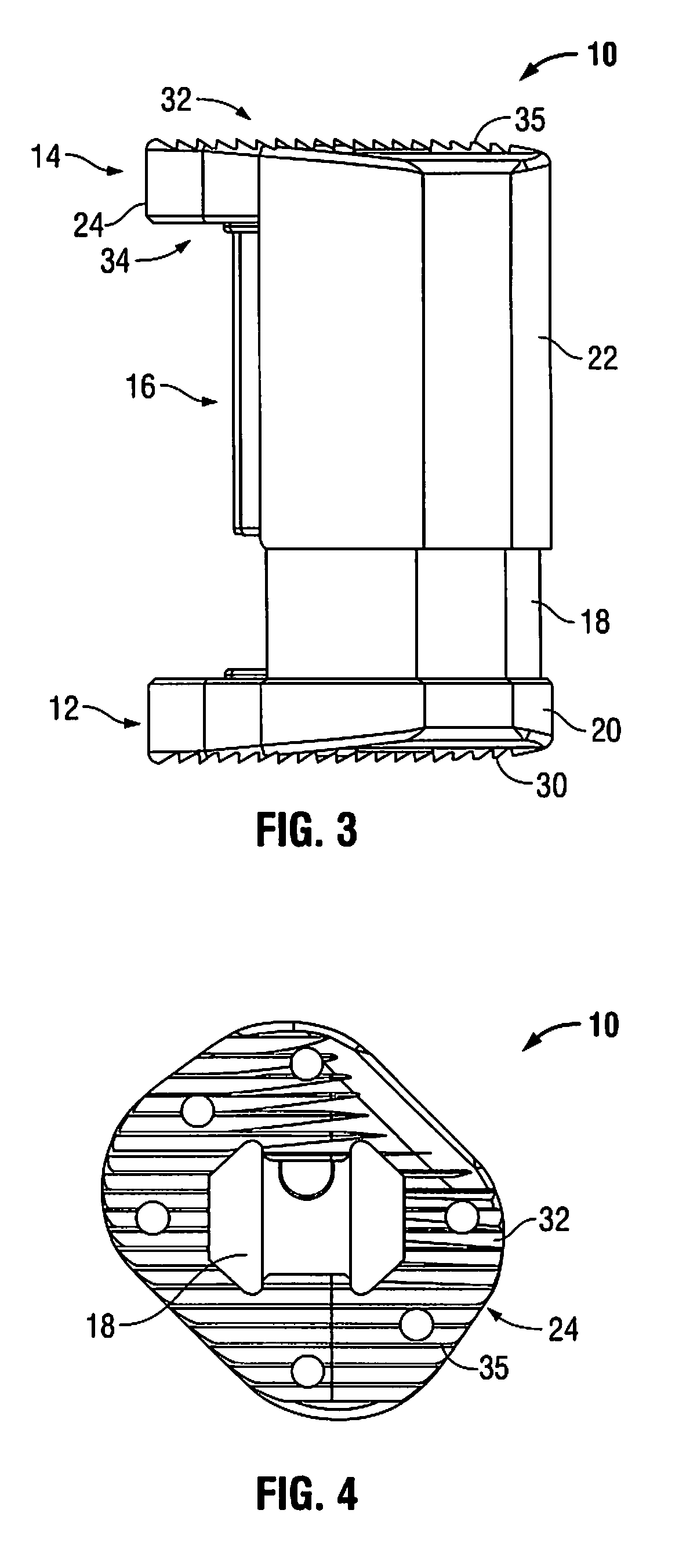
[0044]Embodiments of the presently disclosed devices and methods will now be described in detail with reference to the drawings, wherein like reference numerals identify similar or identical elements. In the drawings and in the description that follows, the term “proximal” will refer to the end of an expandable cage or tool that is closest to the operator, while the term “distal” will refer to the end of the expandable cage or tool that is farthest from the operator. In addition, the term “cephalad” is used in this application to indicate a direction toward a patient's head, whereas the term “caudad” indicates a direction toward the patient's feet. Further still, for the purposes of this application, the term “medial” indicates a direction toward the middle of the body of the patient, whilst the term “lateral” indicates a direction toward a side of the body of the patient (i.e., away from the middle of the body of the patient). The term “posterior” indicates a direction toward the p...


PUM


Abstract

An expandable cage supports adjacent vertebra in spine surgery. The expandable cage includes a first supporting member configured to engage tissue and a second supporting member operatively associated with the first supporting member. The first and second supporting members are movable relative to each other. The expandable cage further includes a cam lock mechanism configured to maintain the first and second supporting members in a fixed relative position. In another embodiment, the expandable cage includes a ring plate lock mechanism in lieu of the cam lock mechanism. The ring plate lock mechanism is adapted to maintain the first and second supporting members in a fixed relative position.

Description

CROSS-REFERENCE TO RELATED APPLICATIONS[0001]The present application claims priority and the benefit of U.S. Provisional Patent Application No. 61 / 063,895, filed on Feb. 7, 2008, and U.S. Provisional Patent Application No. 61 / 086,953, filed on Aug. 7, 2008, each of which is incorporated herein by reference in its entirety.BACKGROUND[0002]1. Technical Field[0003]The present disclosure relates to apparatus and methods for treating spinal conditions and, more particularly, for supporting adjacent vertebrae.[0004]2. Background of Related Art[0005]The human spine includes thirty-three vertebrae. The vertebrae interlock with one another to form a spinal column. Each vertebra has a cylindrical bony body (vertebral body), two pedicles extending from the vertebral body, a lamina extending from the pedicles, two wing-like projections extending from the pedicles, a spinous process extending from the lamina, a pars interarticularis, two superior facets extending from the pedicles, and two infer...

Claims


Application Information

Patent Timeline
IPC IPC(8): A61F2/44
CPCA61F2/44A61F2/442A61F2002/30331A61F2002/30476A61F2002/30495A61F2002/30505A61F2002/3052A61F2002/3055A61F2002/30601A61F2002/30772A61F2002/30904A61F2002/4627A61F2002/4629A61F2220/0025A61F2220/0033A61F2/4455A61F2/4611
Inventor MCCLINTOCK, LARRYSTRAUSS, KEVIN R.DURRANI, ATIQ
Owner K2M
Why Eureka
Try Eureka