

Pressure detection device and pressure detection method
a technology of pressure detection device and pressure detection method, which is applied in the direction of fluid pressure measurement, fluid pressure measurement using inductance variation, instruments, etc., can solve the problem of difficult to make the pressure sensitive element to have the desired shap
- Summary
- Abstract
- Description
- Claims
- Application Information
AI Technical Summary
Benefits of technology
Problems solved by technology
Method used
Image

Examples
first embodiment
A. FIRST EMBODIMENT
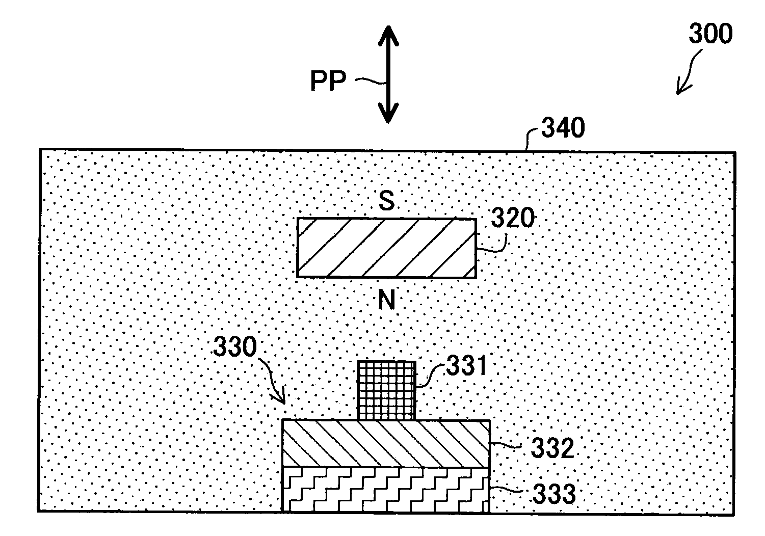
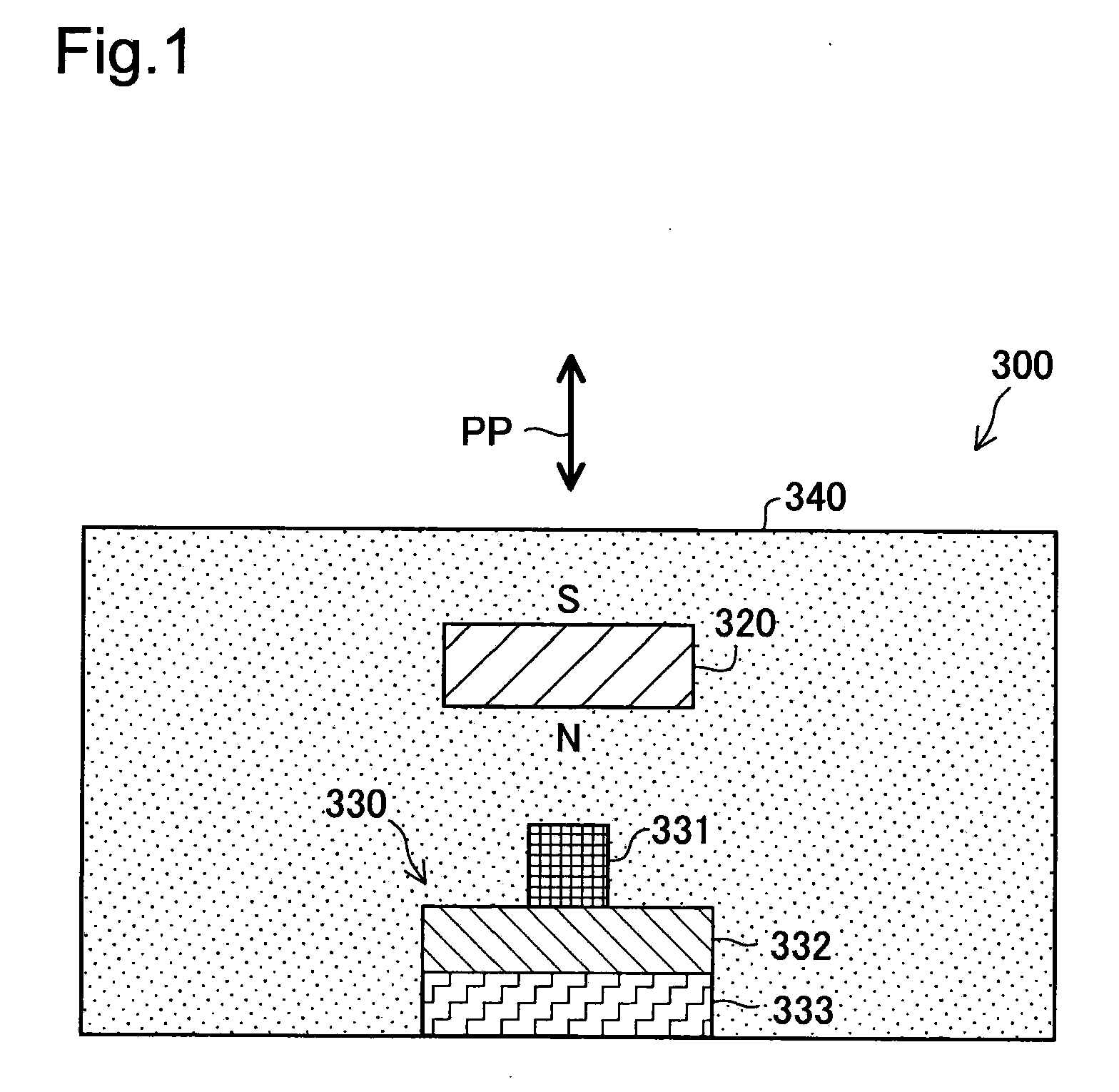
[0044]FIG. 1 schematically illustrates the structure of a pressure detection device 300 in a first embodiment of the invention. The pressure detection device 300 includes a buffer member 340 with a permanent magnet 320 embedded therein, and a sensor assembly 330 provided below the permanent magnet 320. The buffer member 340 is arranged to surround the sensor assembly 330. The permanent magnet 320 is magnetized in a vertical direction in FIG. 1. The sensor assembly 330 has a magnetic sensor circuit 331, a circuit board 332, and a magnetic yoke 333. The magnetic sensor circuit 331 is fixed on the circuit board 332, and the magnetic yoke 333 is disposed on a rear face of the circuit board 332. The magnetic yoke 333 may be omitted when not required. The buffer member 340 is preferably made of a buffer material deformable to absorb an external shock or vibration, such as sponge or polyurethane foam. In the pressure detection device 300 of this structure, in response to...
second embodiment
B. SECOND EMBODIMENT
[0059]FIG. 7 schematically illustrates the structure of a pressure detection device 300a in a second embodiment of the invention. The primary difference from the pressure detection device 300 of the first embodiment shown in FIG. 1 is that a buffer member 340a includes multiple permanent magnets 320 in an evenly dispersed arrangement. Otherwise the structure of the pressure detection device 300a of the second embodiment is similar to the structure of the pressure detection device 300 of the first embodiment. The multiple permanent magnets 320a are preferably formed as tiny articles, such as powder articles, to be evenly dispersed in the buffer member 340a.
[0060]FIG. 8 shows a manufacturing process of the pressure detection device 300a of the second embodiment. At a first step, the buffer member 340a, which is deformable by a pressure change, is provided as shown in FIG. 8A. The buffer member 340 includes tiny non-magnetized magnet members MM. At a second step, t...
third embodiment
C. THIRD EMBODIMENT
[0062]FIGS. 9A and 9B schematically illustrate the structure of a pressure detection device 300b in a third embodiment of the invention. The primary difference from the pressure detection device 300a of the second embodiment shown in FIGS. 7A and 7B is that a sensor assembly 330b includes multiple magnetic sensor circuits 331a and 331b arranged in a lateral direction in FIG. 9A. Otherwise the structure of the pressure detection device 300b of the third embodiment is similar to the structure of the pressure detection device 300a of the second embodiment. The structure of FIG. 9A has the two magnetic sensor circuits 331a and 331b, although the number of magnetic sensor circuits is not restricted to two but may be a greater number. FIG. 9B shows a distribution of pressure to the magnetic sensor circuit 331a and the magnetic sensor circuit 331b under application of an external pressing force PP to the pressure detection device 300b of the third embodiment. The positio...
PUM
 Abstract
Description
Claims
Application Information