Mirror Arrangement for Image Rotation

Inactive Publication Date: 2009-09-10
THOMSON LICENSING SA
View PDF9 Cites 0 Cited by
  • Summary
  • Abstract
  • Description
  • Claims
  • Application Information

AI Technical Summary

Benefits of technology

[0004]The present invention is a mirror arrangement consisting of two or more mirrors that are positioned to rotate an image in a projection system. The two or more mirrors can be any size to accommodate any size image that may be needed. An image beam produced by the projector or any other light source impinges on a first mirror positioned at an angle with respect thereto. This image beam is reflected towards a second mirror positioned at an angle with respect to the first mirror and reflected to a screen or other display source. The end result is that the projected image is rotated with respect to the source projector image in an efficient and inexpensive way.

Problems solved by technology

In some rear-projection devices that make use of digital light projection, a problem can arise regarding the need to rotate each image in the system by 90 degrees.
The problem with this is that many projectors will not operate reliably in a rotated position and this mounting arrangement may require expensive and complicated mounting structures.
Alternatively, using an “off the shelf” optical device such as, for example, a roof prism, can also prove unrealistic due to the high cost of these devices.

Method used


Image

  • Mirror Arrangement for Image Rotation
  • Mirror Arrangement for Image Rotation
  • Mirror Arrangement for Image Rotation

Examples


Embodiment Construction

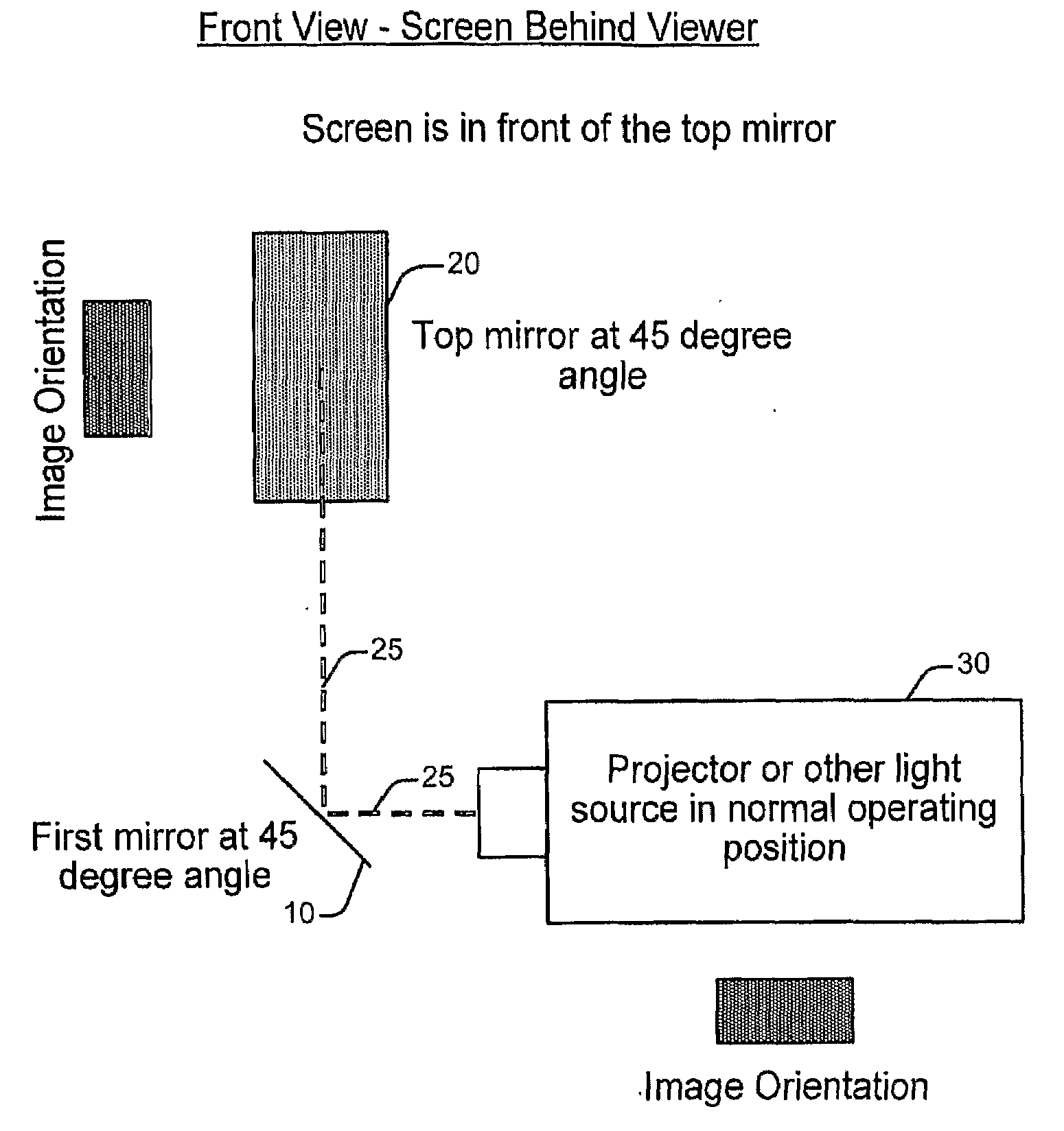
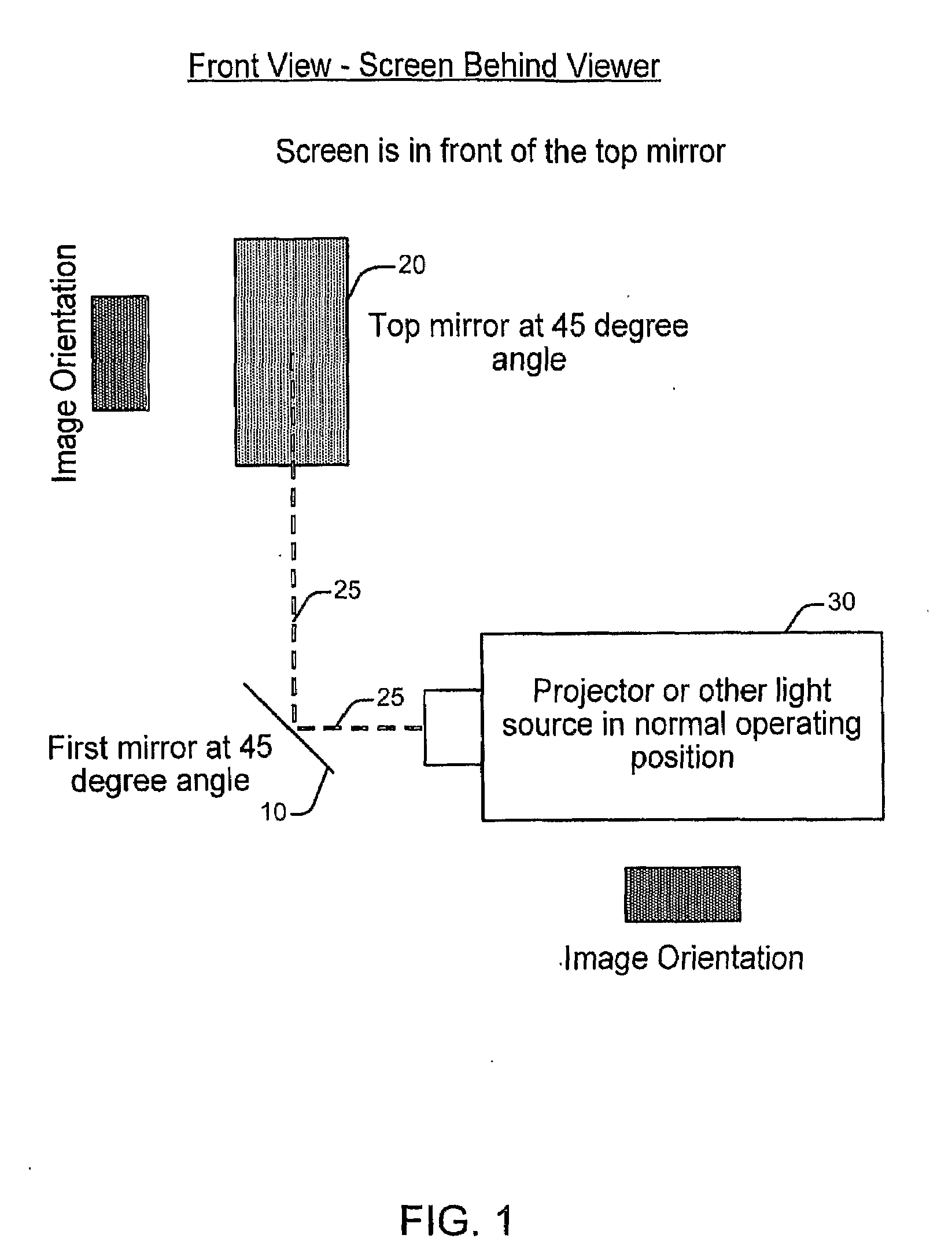
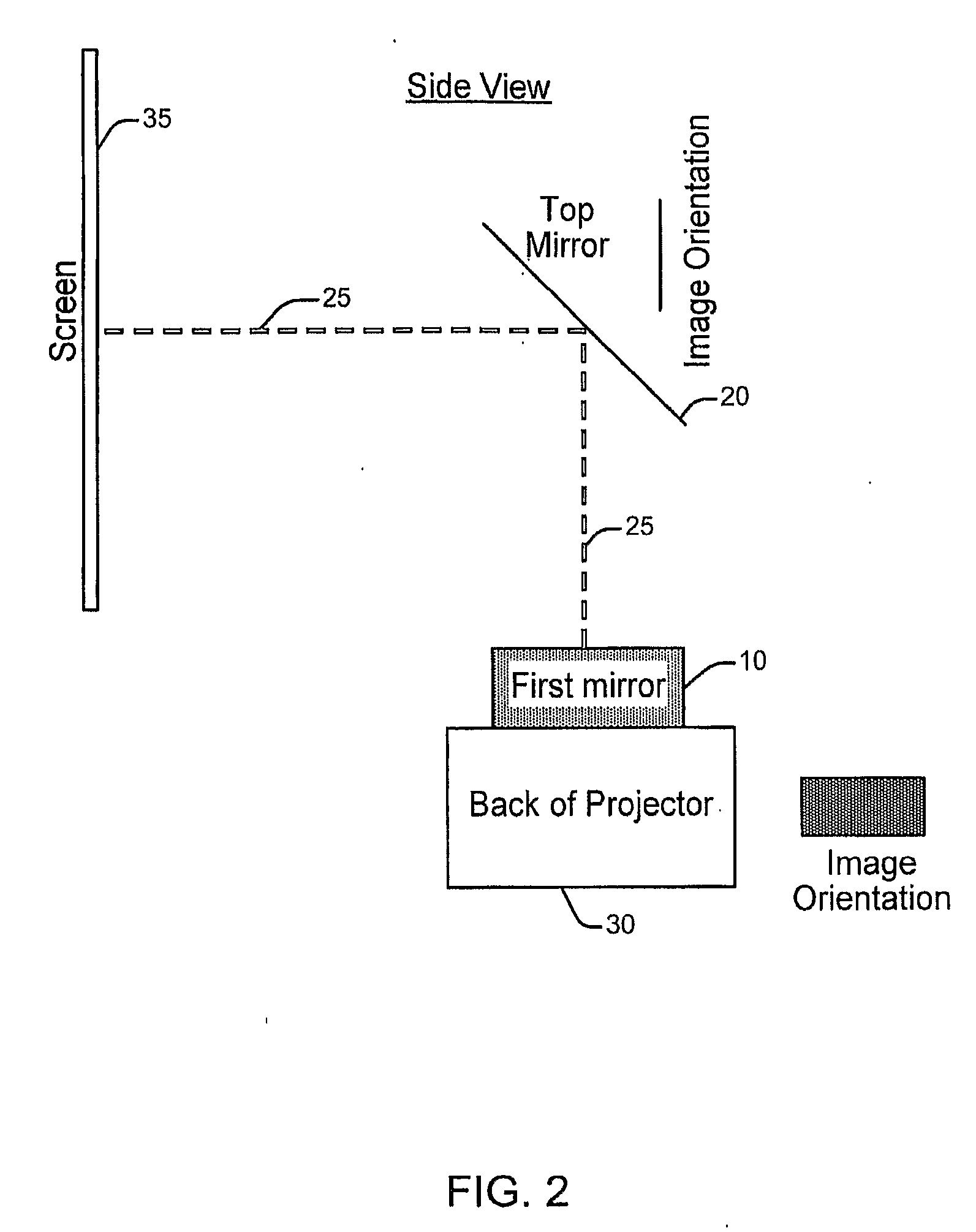
[0008]The present invention is a mirror arrangement consisting of two or more mirrors that are positioned to rotate an image in a projection system. The two or more mirrors can be any size to accommodate any size image that may be needed. An image beam produced by the projector or any other light source impinges on a first mirror positioned at an angle with respect thereto. This image beam is reflected towards a second mirror positioned at an angle with respect to the first mirror and reflected to a screen or other display source. The end result is that the projected image is rotated with respect to the source projector image in an efficient and inexpensive way.

[0009]In one exemplary embodiment two mirrors 10, 20 are used as seen in FIGS. 1 and 2. The two mirrors 10, 20 are arranged at 45 degree angles and turned 90 degrees from each other. An image beam 25 produced by the projector 30 or any other light source impinges on a first mirror 10 positioned at a 45-degree angle with respe...


PUM


Abstract

A mirror arrangement consisting of two or more mirrors that are positioned to rotate an image in a projection system is described. The two or more mirrors can be any size to accommodate any size image that may be needed. An image beam produced by the projector or any other light source impinges on a first mirror positioned at an angle with respect thereto. This image beam is reflected towards a second mirror positioned at an angle with respect to the first mirror and reflected to a screen or other display source. The end result is that the projected image is rotated with respect to the source projector image in an efficient and inexpensive way.

Description

TECHNICAL FIELD[0001]This invention relates to a technique for rotating an image in a projection system.BACKGROUND ART[0002]In some rear-projection devices that make use of digital light projection, a problem can arise regarding the need to rotate each image in the system by 90 degrees. In some systems that combine multiple projectors (e.g., four projectors) into one, the images needed to be displayed in a way that was not intended by the projector manufacturer. Thus, the 16×9 horizontal image that would normally be displayed horizontally, would need to be turned on its side in a vertical 16×9 fashion. This can be accomplished optically, for example, using a roof prism or some other device, using mirrors, or physically rotating the projector in a way that it was not intended to operate.[0003]In the past, the image rotation problem has been solved by physically mounting the projector in a rotated position. The problem with this is that many projectors will not operate reliably in a r...

Claims


Application Information

Patent Timeline
IPC IPC(8): H04N9/31
CPCG02B17/026H04N5/74G02B17/06
Inventor LAMB, MATTHEW ROBERTSCHULTZ, MARK ALAN
Owner THOMSON LICENSING SA
Why Eureka
Try Eureka