Electro-optic displays

a display and optical technology, applied in the field of optical displays, can solve the problems of insufficient service life and the inability to use the display in large numbers, and achieve the effect of preventing the widespread use of the display

Inactive Publication Date: 2009-09-10
E INK CORPORATION
View PDF102 Cites 275 Cited by
  • Summary
  • Abstract
  • Description
  • Claims
  • Application Information

AI Technical Summary

Problems solved by technology

Nevertheless, problems with the long-term image quality of these displays have prevented their widespread usage.
For example, particles that make up electrophoretic displays tend to settle, resulting in inadequate service-life for these displays.

Method used


Image

  • Electro-optic displays
  • Electro-optic displays
  • Electro-optic displays

Examples


Embodiment Construction

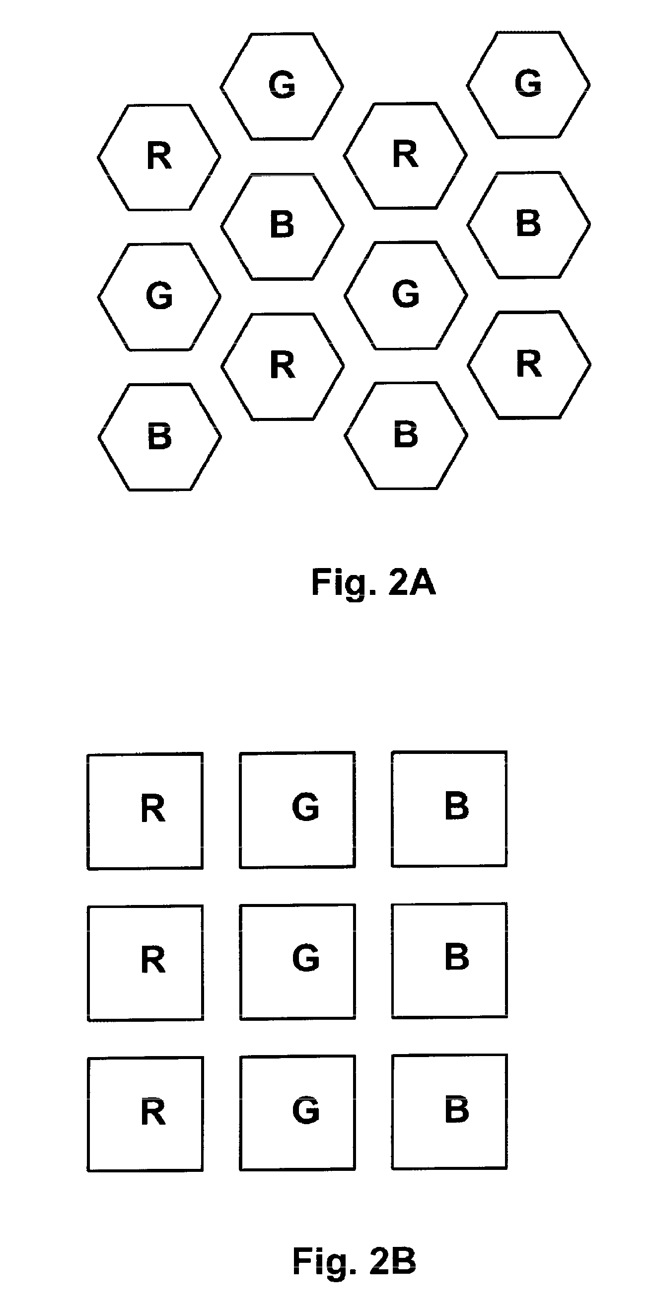
[0076]The present invention provides several different improvements in color filters and other aspects of electro-optic displays, and in ways of generating color in such displays. These various improvements can be used alone or in various combinations (for example, a single display might use a color filter array having non-rectangular pixels produced by the imaging process of the invention. For convenience, the various aspects of the present invention will hereinafter be described separately, but it must always be remembered that multiple aspects of the invention may be used in a single electro-optic display or component thereof.

[0077]Part A—Custom Colors in Electrophoretic Displays

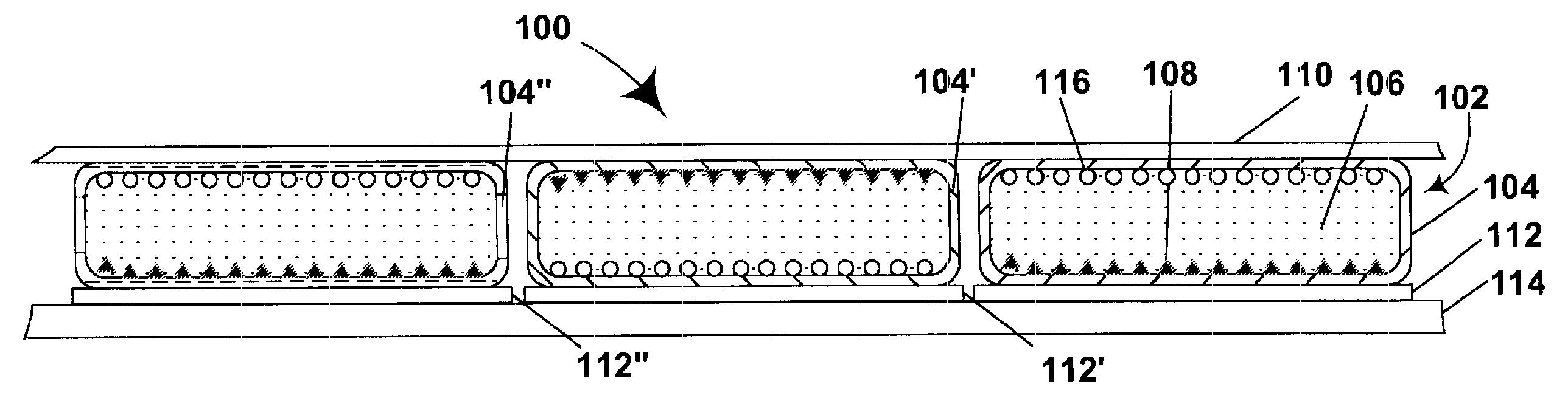
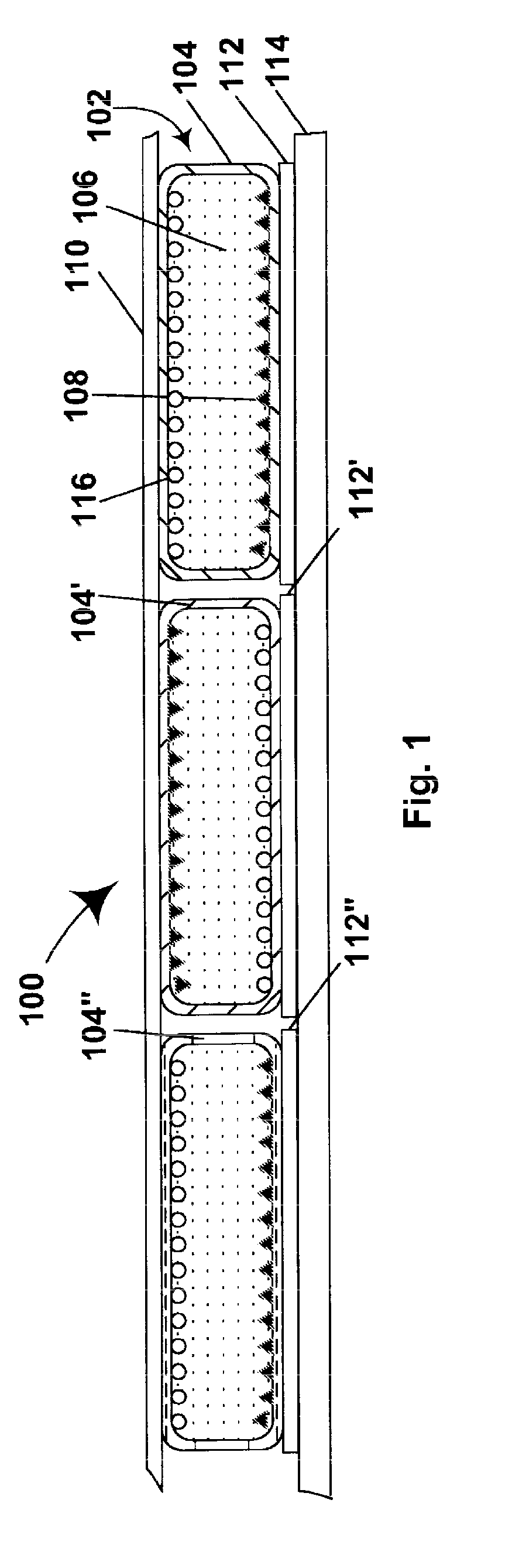
[0078]As discussed in some of the aforementioned E Ink and MIT patents and published applications, in an electrophoretic display one alternative to the use of color filters is to use multiple types of capsules capable of displaying differing colors. For example, the aforementioned 2002 / 0180688 shows, in F...


PUM

PropertyMeasurementUnit
volume resistivityaaaaaaaaaa
diametersaaaaaaaaaa
volume resistivityaaaaaaaaaa

Abstract

The invention provides an electrophoretic medium comprising at least two types of particles having substantially the same electrophoretic mobility but differing colors. The invention also provides article of manufacture comprising a layer of a solid electro-optic medium, a first adhesive layer on one surface of the electro-optic medium, a release sheet covering the first adhesive layer, and a second adhesive layer on an opposed second surface of the electro-optic medium.

Description

REFERENCE TO RELATED APPLICATIONS[0001]This application is a division of application Ser. No. 10 / 605,024, filed Sep. 2, 2003 (Publication No. 2004 / 0155857), which claims priority from Provisional Application Ser. No. 60 / 319,516, filed Sep. 3, 2002.[0002]This application is related to copending application Ser. No. 10 / 143,046 filed May 10, 2002 (Publication No. 2003 / 0011560, now U.S. Pat. No. 7,256,766), which is a continuation-in-part of application Ser. No. 09 / 140,862, filed Aug. 27, 1998 (now U.S. Pat. No. 7,167,155). This application is also related to copending application Ser. No. 10 / 145,861 (Publication No. 2002 / 0180688, now U.S. Pat. No. 6,864,875), which is a continuation of application Ser. No. 09 / 436,303, filed Nov. 8, 1999 (now abandoned), which is turn is a divisional of copending application Ser. No. 09 / 289,507, filed Apr. 9, 1999 (now U.S. Pat. No. 7,075,502), which claims priority from Provisional Application Ser. No. 60 / 081,362, filed Apr. 10, 1998. This application ...

Claims


Application Information

Patent Timeline
Patent Type & Authority Applications(United States)
IPC IPC(8): G02F1/167G02F1/01G03F1/00C09K3/00B05D5/00B32B37/02G02B5/20G02F1/1333G02F1/1334G02F1/1335G02F1/16757G02F1/1677G02F1/1679
CPCG02F1/1334G02F1/133514G02F1/167G02F2001/1678G02F1/133348G02F1/133516G02F2001/133354G02F2202/28G02F1/1679G02F1/1677G02F1/16757G02F1/133354G02F2201/52
Inventor DUTHALER, GREGG M.AMUNDSON, KARL R.GATES, HOLLY G.RITLER, JOHN E.WILCOX, RUSSELL J.ZEHNER, ROBERT W.COMISKEY, BARRETTGOENAGA, ALBERTOSTEINER, MICHAEL L.PULLEN, ANTHONY EDWARD
Owner E INK CORPORATION
Why Eureka
Try Eureka