
Eureka
For R&D, Eureka makes reading and utilizing patents & technical documents easy.
Eureka AIR
Designed for self-driven R&D workflows. Generate viable solutions, solve complex R&D challenges, empower your innovation with AI.

Eureka Materials
Designed for material experts only. Revolutionize your material R&D, from search, analyze, to developing new materials.

TechResearch
Generate reliable direction feasibility study reports for your R&D in just a few steps.

TechSeek
Discover and master advanced knowledge NOW. Basics, ideas, possibilities, all at once.

TechMind
As an expert in R&D Theories, TechMind can generates customized viable solutions instantly.

TechRisk
Analyze your overall solution with one click, know your potential R&D risks in advance.

TechMonitor
Get weekly tech updates, stay abreast of the latest tech innovations and key insights.
Gate driving module and LCD thereof
- Summary
- Abstract
- Description
- Claims
- Application Information
AI Technical Summary
Benefits of technology
Problems solved by technology
Method used
Image

Examples
first embodiment
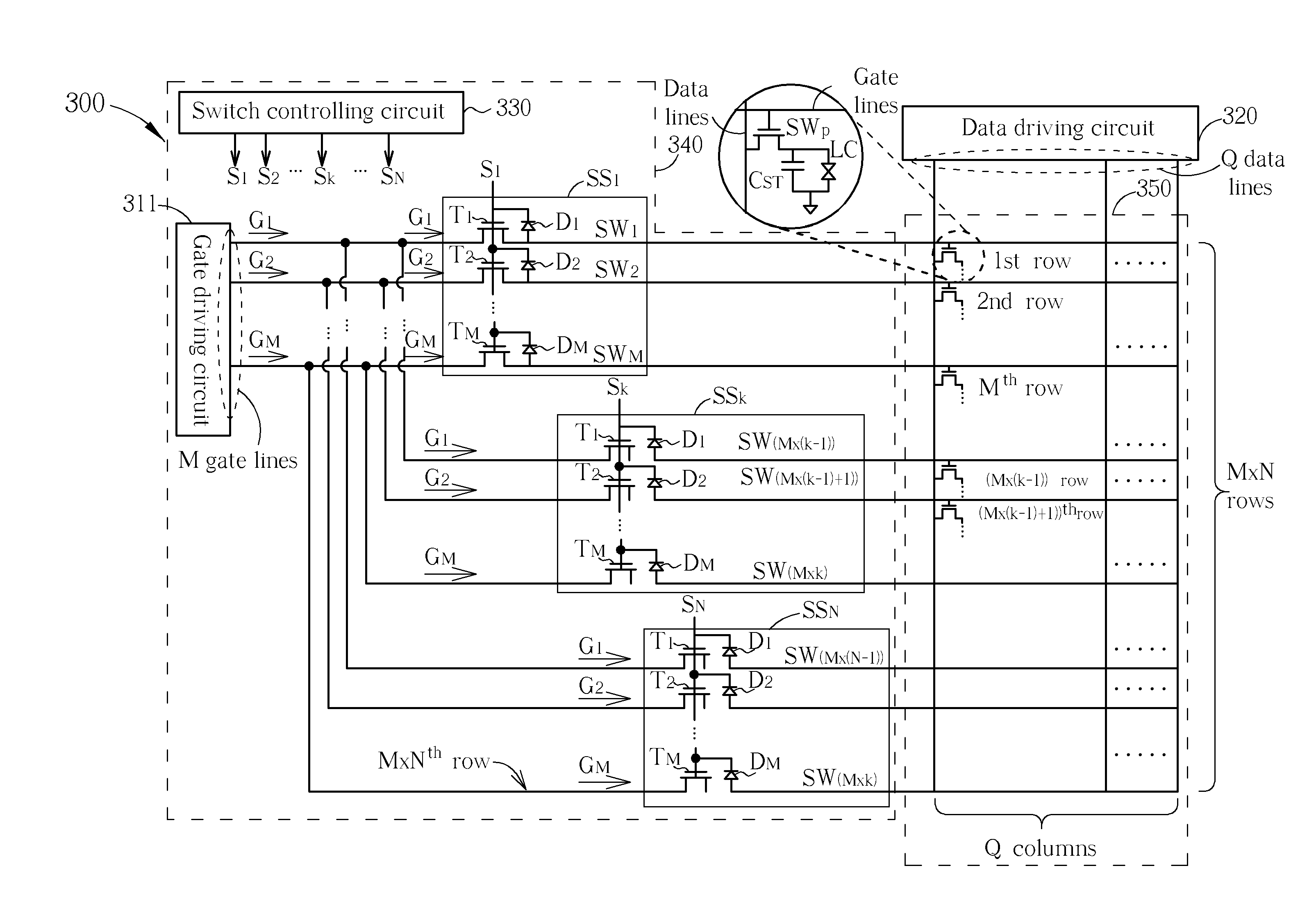
[0014]Please refer to FIG. 3. FIG. 3 is an LCD 300 according to the present invention. As shown in FIG. 3, the LCD 300 comprises a gate driving module 340, a data driving circuit 320, and a pixel area 350. The data driving circuit 320 comprising Q data lines (output ends) outputs Q data signals respectively. The pixel area 350 is constructed by Q(column)×(M×N)(row) pixels. That is, the highest resolution of the LCD 300 is Q×M×N. Each pixel of the pixel area 350 comprises a first switch unit SWP, a storing capacitor CST, and a corresponding liquid crystal layer area LC. The first switch unit SWP comprises a first end, a second end, and a control end. The first end of the first switch unit SWP coupled to a corresponding data line of the data driving circuit 320 receives corresponding data signal. The second end of the first switch unit SWP is coupled to the storing capacitor CST and the corresponding liquid crystal layer area LC. The control end of the first switch unit SWP coupled to...
second embodiment
[0023]Please refer to FIG. 5. FIG. 5 is a diagram illustrating an LCD 500 according to the present invention. The LCD 500 is similar to the LCD 300. The only difference between the LCDs 500 and 300 is that an additional gate driving circuit 312 is added in the LCD 500. The gate driving circuits 311 and 312 can be respectively disposed in the different areas of the LCD 500, e.g. upper part of the LCD 500 and the lower part of the LCD 500. The deployment of the gate driving circuit 311 and 312 reduces the degeneration and the delay of the gate driving signals caused by the lengths of the driving paths. In this way, even if the display size of the LCD 500 increases, the frames displayed thereon still have high quality.
[0024]In the fabrication process of the LCD, since the first switch unit (for pixel) and the second switch unit (for switching gate driving signal) are fabricated in the same process, the overall cost of the LCD does not increase. Compared to the LCD of the present invent...
PUM
 Abstract
Description
Claims
Application Information
 - R&D Engineer
- R&D Manager
- IP Professional
- Industry Leading Data Capabilities
- Powerful AI technology
- Patent DNA Extraction
Browse by: Latest US Patents, China's latest patents, Technical Efficacy Thesaurus, Application Domain, Technology Topic, Popular Technical Reports.
© 2024 PatSnap. All rights reserved.Legal|Privacy policy|Modern Slavery Act Transparency Statement|Sitemap|About US| Contact US: help@patsnap.com