LED lamp assembly

a technology of led lamps and assembly parts, which is applied in the direction of fixed installation, lighting and heating equipment, lighting support devices, etc., can solve the problems of increasing production costs, unduly time-consuming, and the direction of the light emitted by the led lamp cannot be changed to meet different requirements

Inactive Publication Date: 2009-09-24
FU ZHUN PRECISION IND SHENZHEN +1
View PDF5 Cites 36 Cited by
  • Summary
  • Abstract
  • Description
  • Claims
  • Application Information

AI Technical Summary

Problems solved by technology

However, once the LED lamp is fixed under a determined circumstance, a direction of a light emitted by the LED lamp cannot be changed to meet different requirements.
Ge...

Method used


Image

  • LED lamp assembly
  • LED lamp assembly
  • LED lamp assembly

Examples


Embodiment Construction

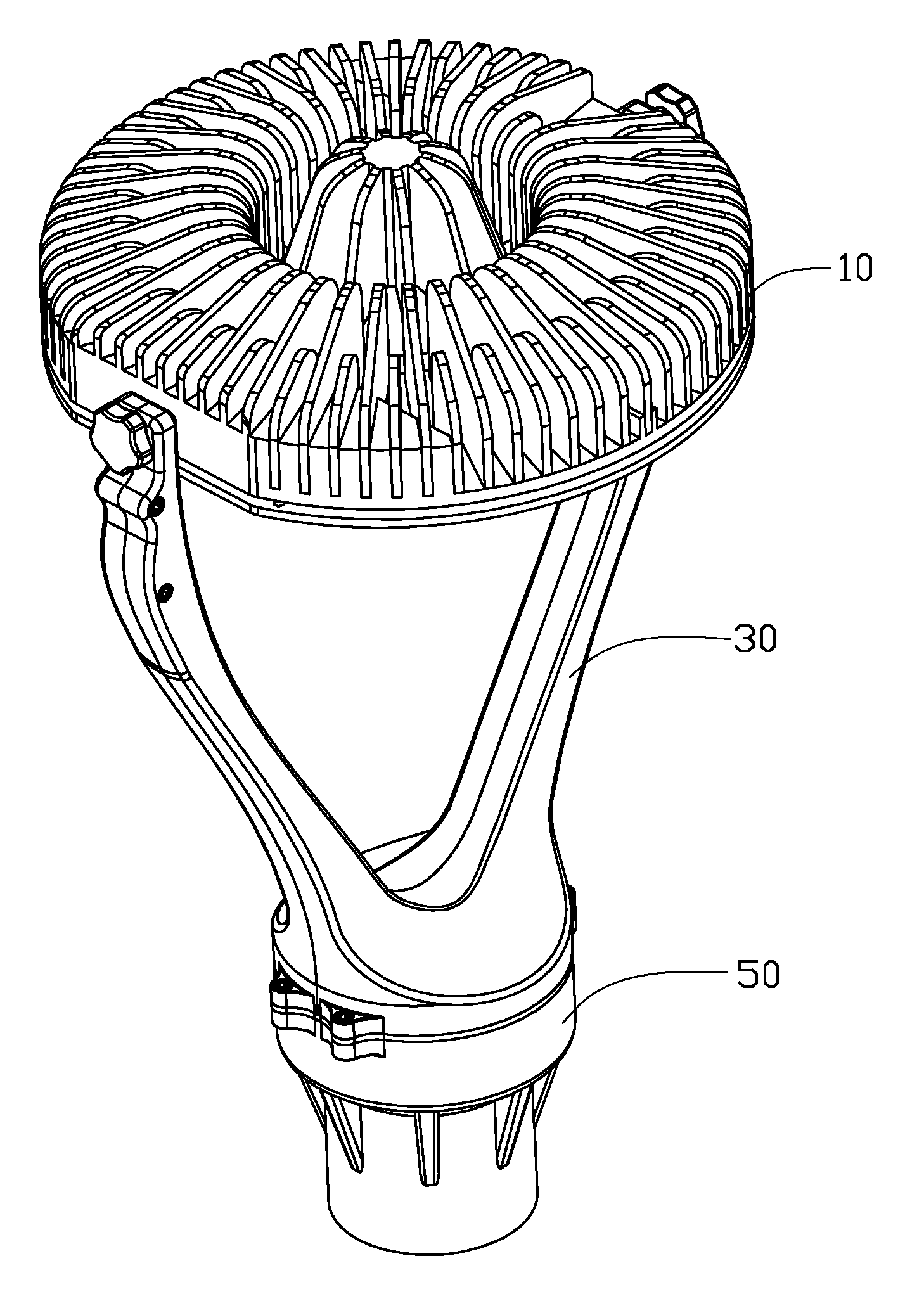
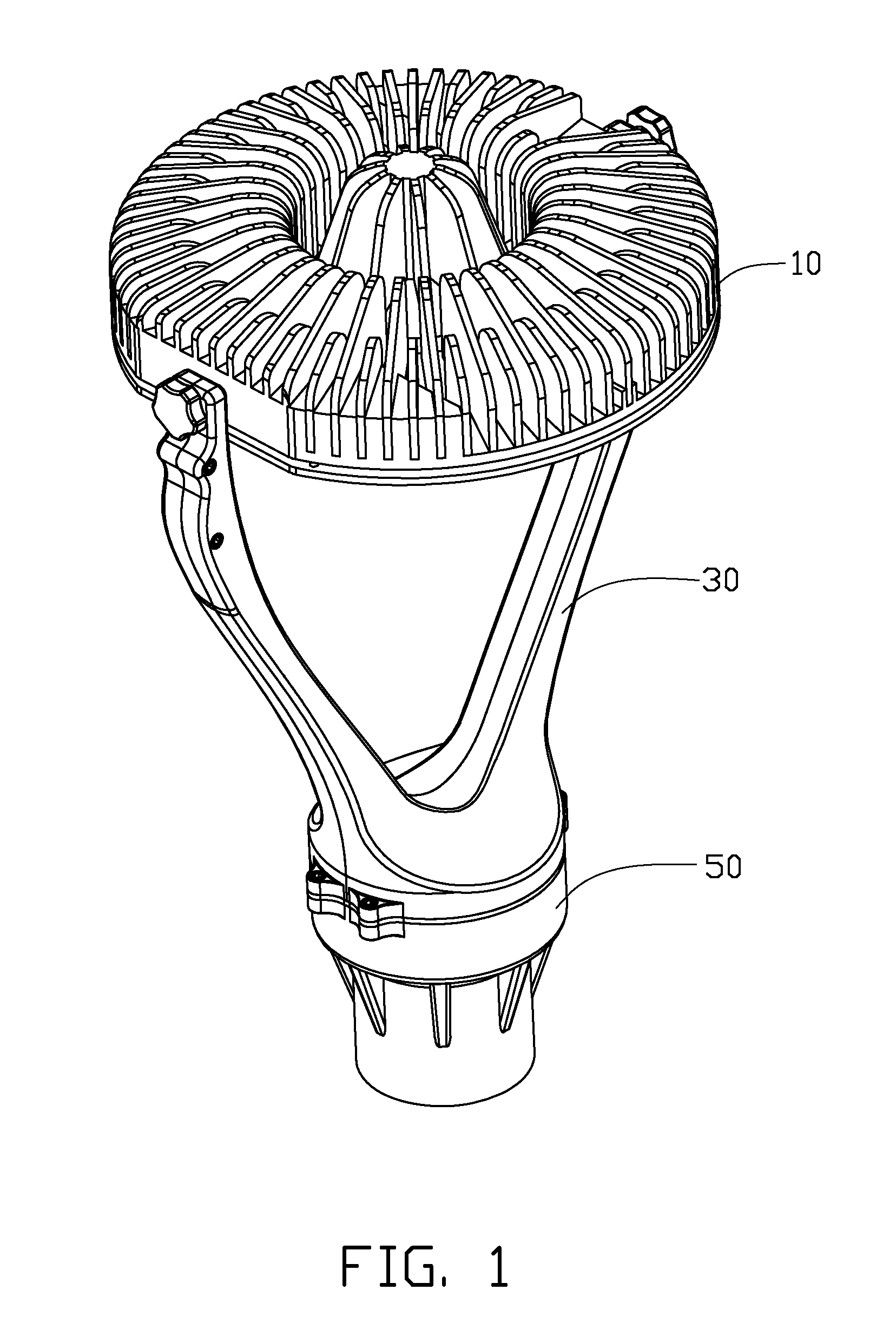
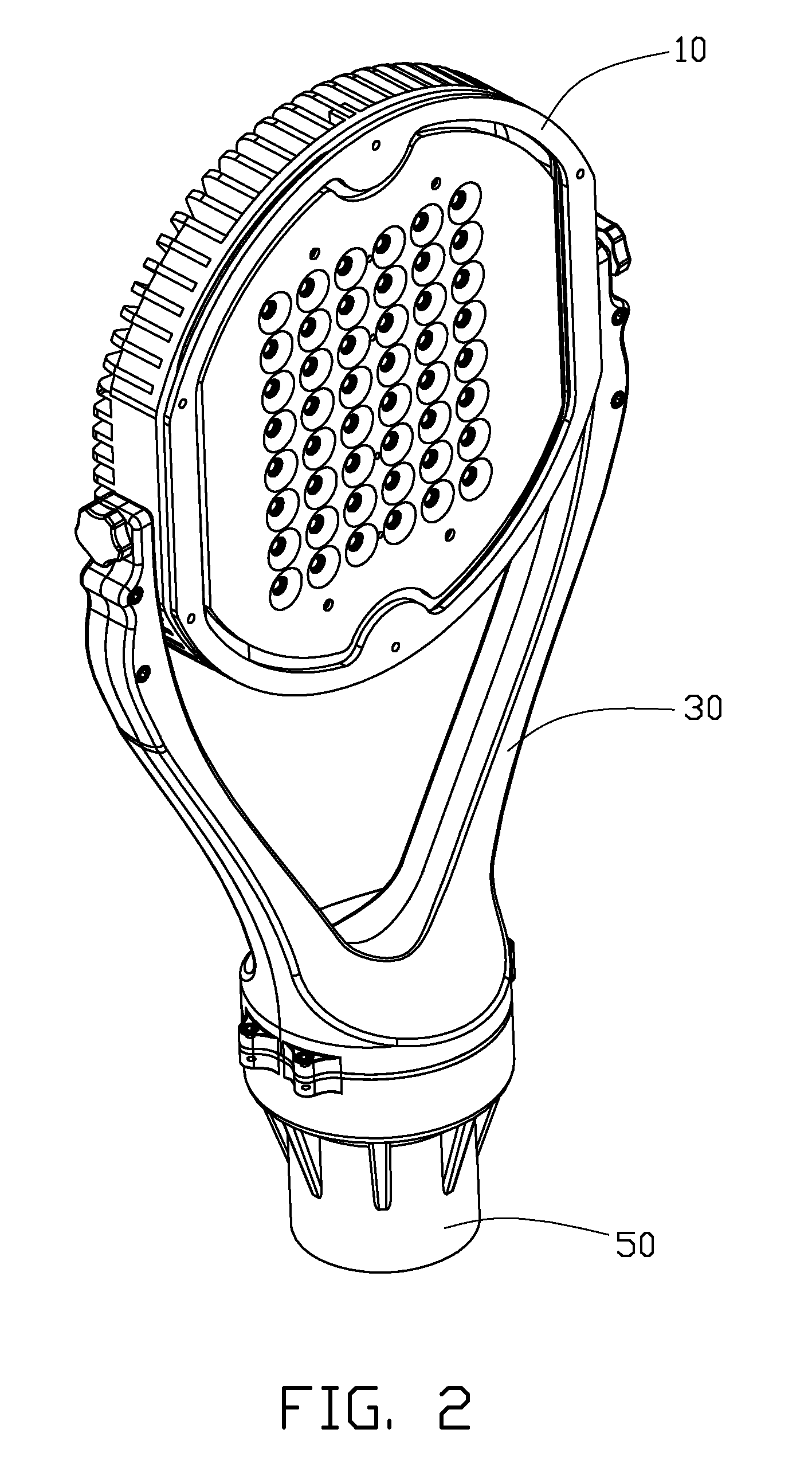
[0014]Referring to FIGS. 1-2, an LED lamp assembly in accordance with a preferred embodiment of the present invention comprises an LED lamp 10, a supporting member 30 supporting the LED lamp 10 and a fixture 50. The supporting member 30 is mounted on the fixture 50. A driving circuit module (not shown) is received in the fixture 50 to electronically connect with the LED lamp 10. In addition, a supporting post (not shown) is connected to the fixture 50 to support the LED lamp assembly at a desired position.

[0015]Referring to FIGS. 3-4 also, the LED lamp 10 comprises a plurality of LED modules 12, a heat sink 11 supporting and cooling the LED modules 12, a reflector 13 mounted on the heat sink 11 and spanning the LED modules 12, a transparent envelope 15 attached to the heat sink 11 and covering the reflector 13 and the LED modules 12 and a ring 14 pressing the envelope 15 toward the heat sink 11.

[0016]The heat sink 11 is supported by the supporting member 30. The heat sink 11 has a d...


PUM


Abstract

An LED lamp assembly includes an LED lamp and a supporting member supporting the LED lamp. The LED lamp includes a plurality of LED modules and a heat sink supporting and cooling the LED modules. The supporting member includes a pair of supporting arms supporting the LED lamp and pivotably engaging with the heat sink of the LED lamp. The heat sink is rotatable relative to the supporting arms of the supporting member to vary an illumination angle of the LED lamp assembly.

Description

BACKGROUND OF THE INVENTION [0001]1. Field of the Invention[0002]The present invention relates to an LED lamp assembly, and more particularly to an LED lamp assembly having an LED lamp which is rotatable to assume various angles of illumination.[0003]2. Description of Related Art[0004]The technology of light emitting diodes has rapidly developed in recent years from indicators to illumination applications. With the features of long-term reliability, environment friendliness and low power consumption, the LED is viewed as a promising alternative for future lighting products.[0005]A conventional LED lamp comprises a heat sink and a plurality of LED modules having LEDs attached to an outer surface of the heat sink to dissipate heat generated by the LEDs. The outer surface of the heat sink generally is a plane and the LEDs are arranged close to each other. When the LED lamp works, the LEDs mounted on the planar outer surface of the heat sink only form a flat light source. However, once ...

Claims


Application Information

Patent Timeline
IPC IPC(8): F21S4/00F21V21/14F21V29/00
CPCF21V21/30F21V29/004F21V29/773F21Y2105/001F21S8/088F21Y2101/02F21Y2105/10F21Y2115/10
Inventor ZENG, JUN-HUACHEN, YONG-DONGWUNG, SHIH-HSUN
Owner FU ZHUN PRECISION IND SHENZHEN
Why Eureka
Try Eureka