Method and apparatus of camera control

Active Publication Date: 2009-10-22
TRACE OPTICS
View PDF13 Cites 20 Cited by
  • Summary
  • Abstract
  • Description
  • Claims
  • Application Information

AI Technical Summary

Benefits of technology

[0020]Preferably, the zoom

Problems solved by technology

One of the difficulties with currently available systems is that the human operator may both miss action and incorrectly operate the camera.
Furthermore, the cost associated with having to employ human operators for most camera

Method used


Image

  • Method and apparatus of camera control
  • Method and apparatus of camera control
  • Method and apparatus of camera control

Examples


Embodiment Construction

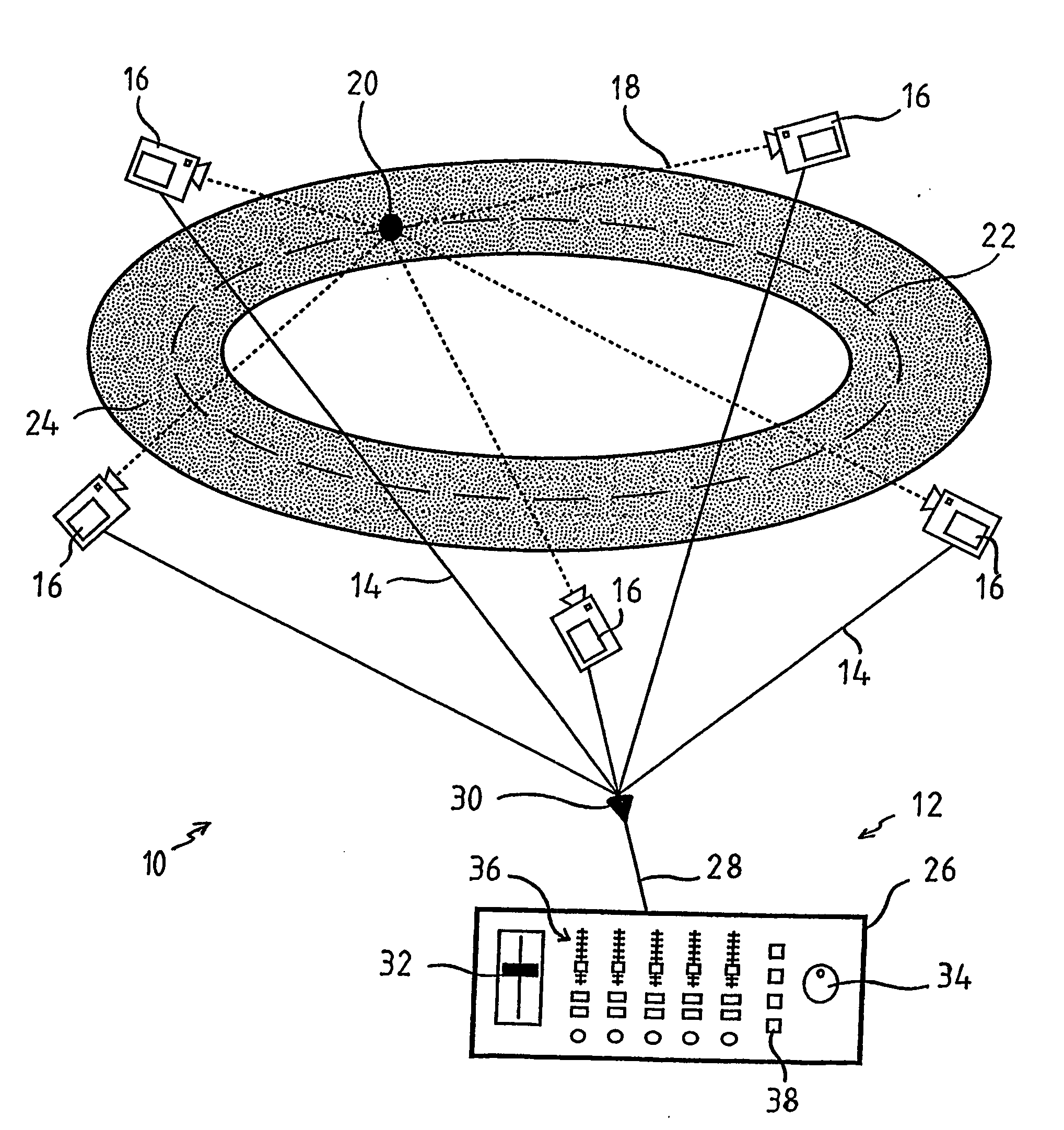
[0061]The following detailed description of the invention refers to the accompanying drawings. Although the description includes exemplary embodiments, other embodiments are possible, and changes may be made to the embodiments described without departing from the spirit and scope of the invention. Wherever possible, the same reference numbers will be used throughout the drawings and the following description to refer to the same and like parts. Referring to the drawings for a more detailed description, a camera control system 10 is illustrated in FIG. 1, demonstrating by way of example one arrangement in which the principles of the present invention may be employed. The camera control system 10 includes a control apparatus 12 which is in communication 14 with a plurality of cameras 16. The control apparatus 12 is configured to control the movement of the cameras 16 to simultaneously train their respective centre lines 18 on a node 20 while automatically adjusting the field of view 7...


PUM


Abstract

The present invention relates to an automated camera control system (10). The automated camera control system (10) is a control management system for television broadcasting at a track based event, such as horse or motor racing. The automated camera control system (10) allows a single operator (54) to simultaneously control a plurality of cameras (16). The automated camera control system (10) improves the compositional quality of the footage. The operator (54) can simultaneously perform all the functions of a director including vision switching and camera setting for the outgoing television broadcast (86).

Description

CROSS REFERENCE TO RELATED APPLICATION[0001]This application is a national stage of PCT / AU2005 / 001302 filed Aug. 30, 2005, under the International Convention.FIELD OF THE INVENTION[0002]The present invention relates to a camera control system.BACKGROUND OF THE INVENTION[0003]Sporting events have become popular with television audiences as the program provides superior coverage of the event. This is particularly true in sporting events such as motor racing where a spectator at the event is only able to glimpse a small part of the action. Television networks utilise a plurality of cameras at such events in an attempt to provide the best coverage for viewers, including car mounted, aerial, and tripod mounted and mobile cameras.[0004]Typically a human operator is required to manually operate each camera.[0005]Usually, these cameras are deliberately placed at particular locations around a race course in order to capture the best footage of the race. One of the difficulties with currently...

Claims


Application Information

Patent Timeline
IPC IPC(8): H04N7/18H04N5/262H04N5/228
CPCH04N5/222H04N5/232H04N7/185H04N7/181H04N5/247H04N23/661H04N23/695H04N23/90
Inventor ANDERSON, JEREMY L.
Owner TRACE OPTICS
Why Eureka
Try Eureka