Die stamping system

a stamping system and stamping plate technology, applied in the field of die stamping plate, can solve the problems of reducing the strength and aesthetic appearance of the workpiece, and achieve the effect of improving the aesthetic appearance and strength of the workpi

Inactive Publication Date: 2009-10-29
HONG FU JIN PRECISION IND (SHENZHEN) CO LTD +1
View PDF11 Cites 8 Cited by
  • Summary
  • Abstract
  • Description
  • Claims
  • Application Information

AI Technical Summary

Problems solved by technology

However, the location configuration 1 may decrease the strength and aesthetic appearance of the workpiece 2.

Method used


Image

  • Die stamping system
  • Die stamping system
  • Die stamping system

Examples


Embodiment Construction

[0014]A detailed explanation of a die stamping system according to an exemplary embodiment of the present invention will now be made with references to the drawings attached hereto.

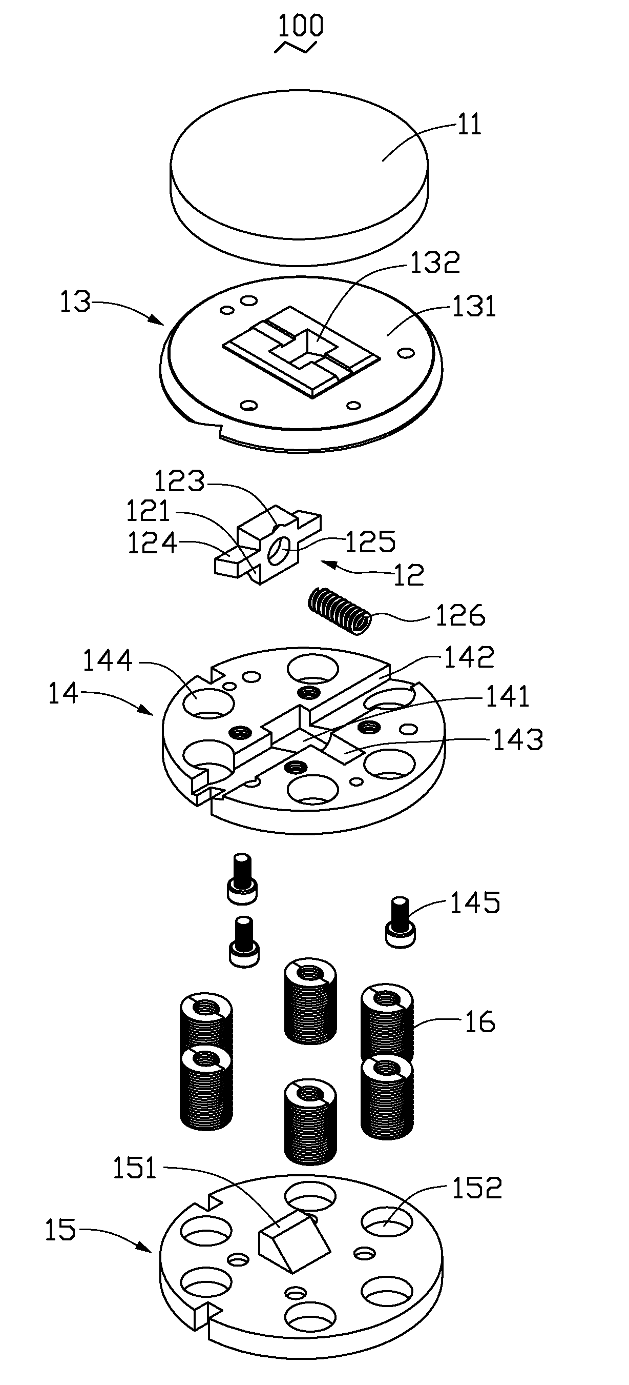
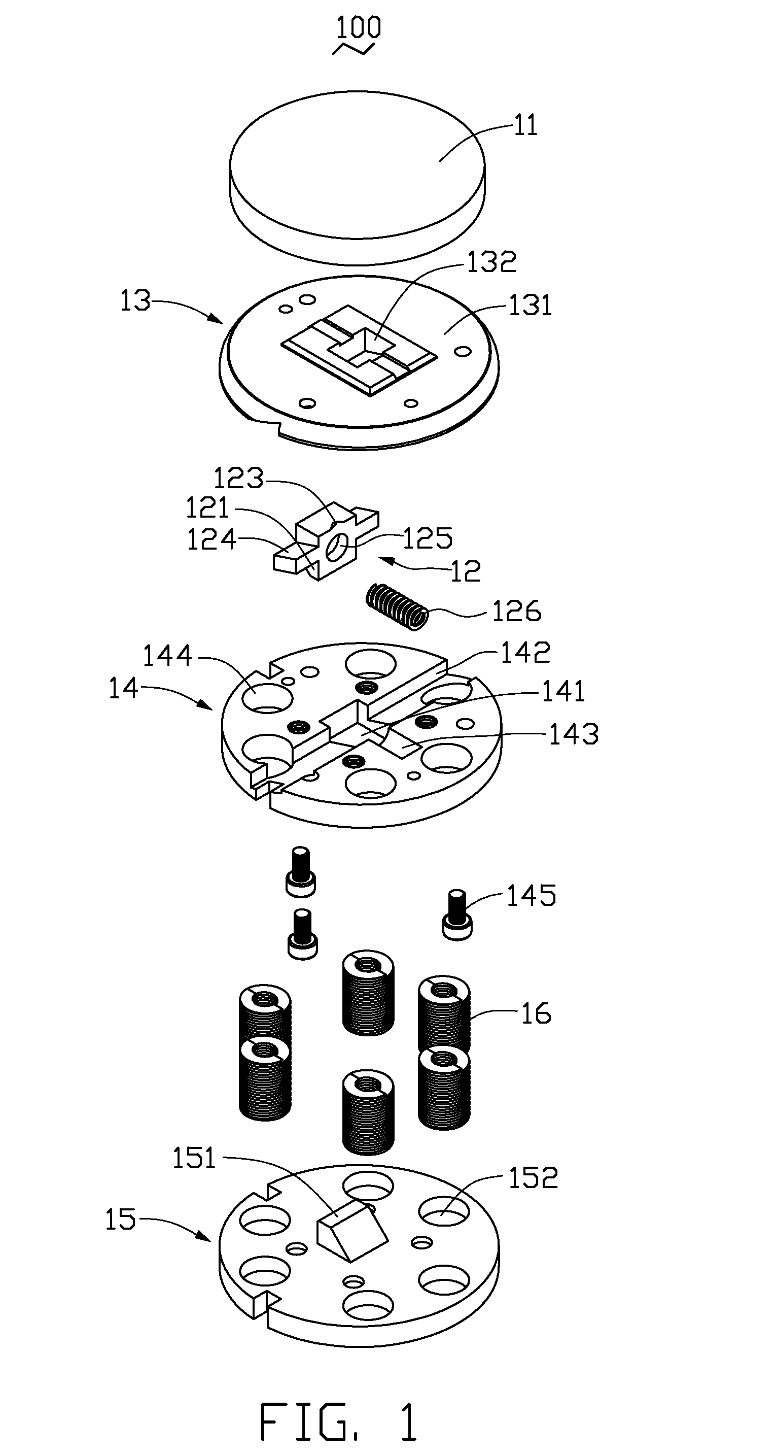
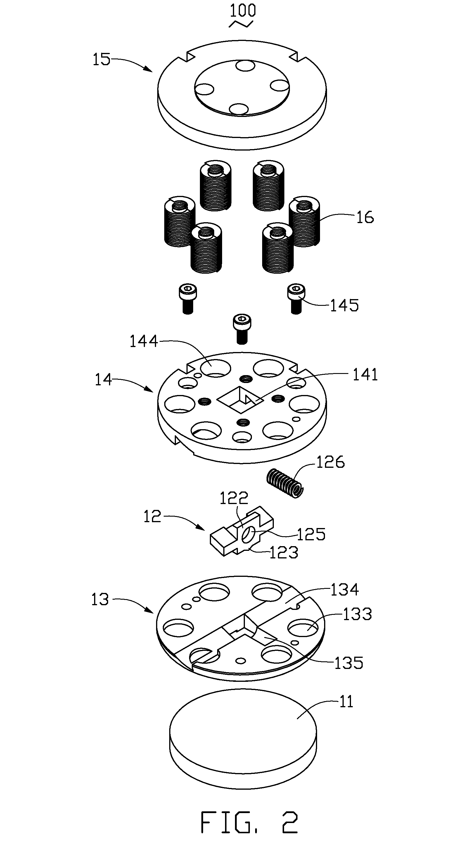
[0015]Referring to FIGS. 1-4, a die stamping system 100 according to an exemplary embodiment of the present embodiment is shown. The die stamping system 100 includes an upper die 11, a sliding block 12, a lower stripper 13 movable with respect to the upper die 11, a die holder 14 connected to the lower stripper 13, and a lower die-set 15 connected to the die holder 14, and more than two ejection springs 16 disposed between the lower stripper 13 and the lower die-set 15. The upper die 11 is connected to a stamping molding machine (not shown) after being matched with a die face 131 of the lower stripper 13 therebetween.

[0016]The sliding block 12 includes a body 121 with a wedge-shaped head 122 facing the lower die-set 15, a punch 123 formed on the body 121, and two arms 124 on opposite sides of the body 121...


PUM

PropertyMeasurementUnit
total axial lengthaaaaaaaaaa
axial lengthaaaaaaaaaa
strengthaaaaaaaaaa

Abstract

A die stamping system includes an upper die, a sliding block, a lower stripper, a die holder connected to the lower stripper, and a lower die-set moveably connected to the die holder. The sliding block includes a body with a wedge-shaped head facing down, a punch connected to the body, and two arms on opposite sides of the body, respectively. The lower stripper matches the upper die-set and has an aperture for passage of the punch therethrough. The die holder is connected to the lower stripper and includes an opening for passage of the body therethrough, and a first notch receiving the two arms. The first notch is larger than the arms. The lower die-set is movably connected to the die holder and includes a wedge-shaped padding block facing up and supporting the wedge-shaped head of the body.

Description

BACKGROUND[0001]1. Technical Field[0002]The present invention relates to a die stamping system and, particularly, to a die stamping system having a sliding block with a punch.[0003]2. Description of Related Art[0004]The objective of a typical fine die stamping apparatus is accurate cutting and punching of a workpiece. Such apparatus usually includes an upper die and a lower die, with one or more punches associated with the upper die and a punch base associated with the lower die, movable with respect to the lower die. To ensure necessary precision during formation of parts, it is common to provide a locating configuration in a workpiece. Referring to FIG. 5, a conventional locating configuration 1 of a workpiece 2 is shown. The location configuration 1 of the workpiece 2 is formed by means of a conventional half-cut punch method. However, the location configuration 1 may decrease the strength and aesthetic appearance of the workpiece 2.[0005]It is desired to provide a die stamping s...

Claims


Application Information

Patent Timeline
Patent Type & Authority Applications(United States)
IPC IPC(8): B26D7/06
CPCB21D28/34B26F1/44B26F1/40B26D7/1818Y10T83/2133Y10T83/8776Y10T83/9476Y10T83/9486
Inventor ZHOU, SHU-WEIHUANG, FU-SHUNOU, CHIA-HSIANG
Owner HONG FU JIN PRECISION IND (SHENZHEN) CO LTD
Why Eureka
Try Eureka