Bimetal Laminate Structure And Method Of Making The Same

a laminate structure and metal technology, applied in the field of metalpolymermetal laminates, can solve the problems of reducing the thickness of the monolithic metal substrate, reducing the robustness of the decorative surface, and limiting the use of certain monolithic metal substrates to achieve the desired “finished metallic look” for the decorative surface, etc., to achieve the effect of reducing the cost of expensive monolithic metal substrates, eliminating substantially all facial defects, and less expensiv

Active Publication Date: 2009-10-29
MATERIAL SCIENCES CORPORATION
View PDF19 Cites 6 Cited by
  • Summary
  • Abstract
  • Description
  • Claims
  • Application Information

AI Technical Summary

Benefits of technology

[0007]The present invention provides a metal-adhesive-metal laminate, and a method of manufacturing the same, which reduces the cost of expensive monolithic metal substrates, such as, but not limited to, stainless steel, titanium, brass, nickel, and copper. The methods of the present invention eliminate substantially all facial defects and read through appearance on the decorative surface of the metal laminate, which might otherwise be expected when using an adhesive beneath a thin sheet

Problems solved by technology

However, the use of certain monolithic metal substrates to provide the desired “finished metallic look” for the decorative surface may be limited due to the high cost of the metallic materials—e.g., titanium, stainless steel, nickel, copper, and other expensive metal sheet stock.
However, reducing the thickness of the monolithic metal substrate may eventually reduce its robustness (e.g., reducing structural or surface integrity), and may eliminate certain post processing operations, such as brushing, polishing, embossing, or other decorative finishes imparted by mechanical means, due to minimal thickness requirements.
Unfortunately, the electroplated surface will read through (or telegraph) the appearance of the substrate surface to which it is coating.
Moreover, the extremely

Method used


Image

  • Bimetal Laminate Structure And Method Of Making The Same
  • Bimetal Laminate Structure And Method Of Making The Same
  • Bimetal Laminate Structure And Method Of Making The Same

Examples


Embodiment Construction

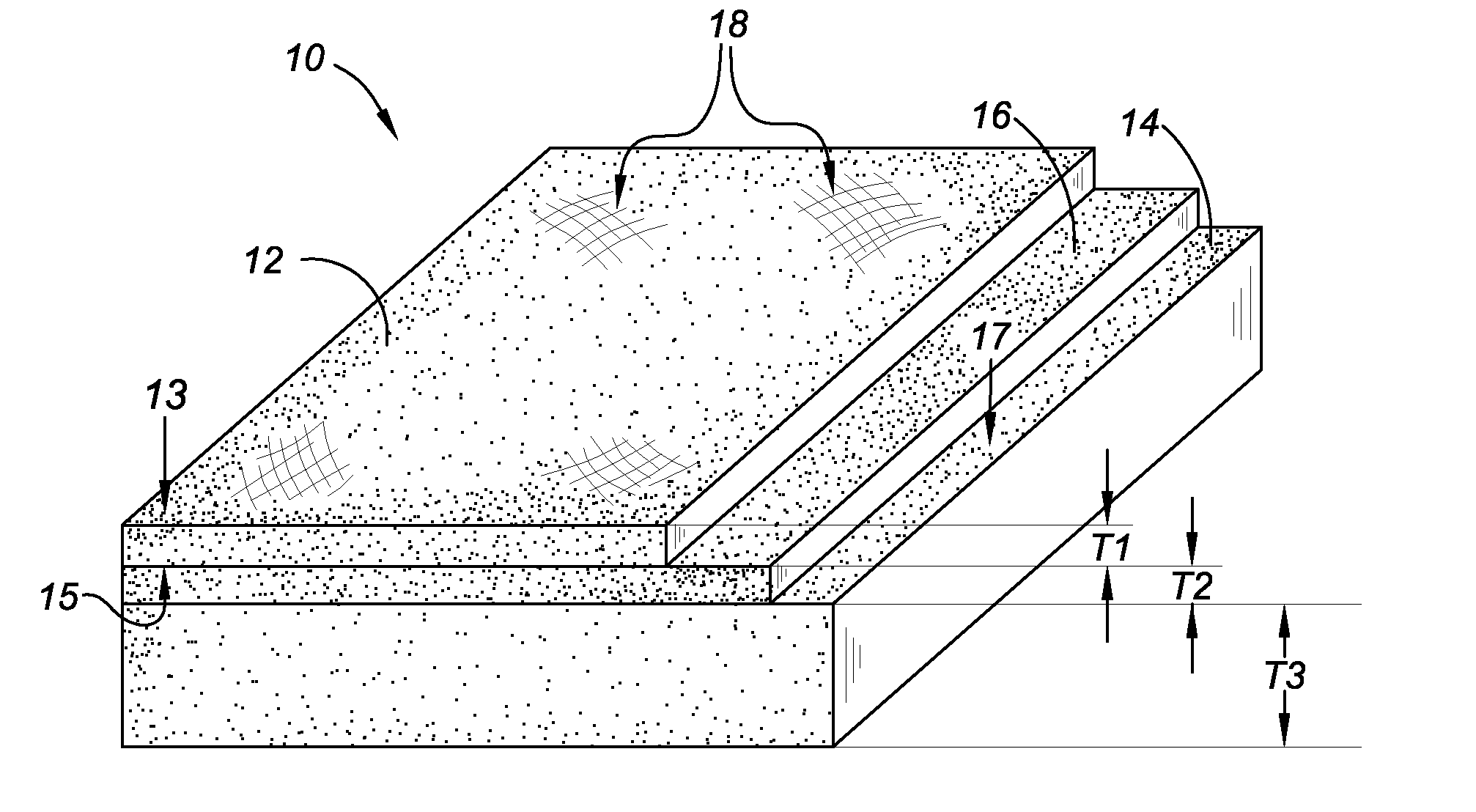
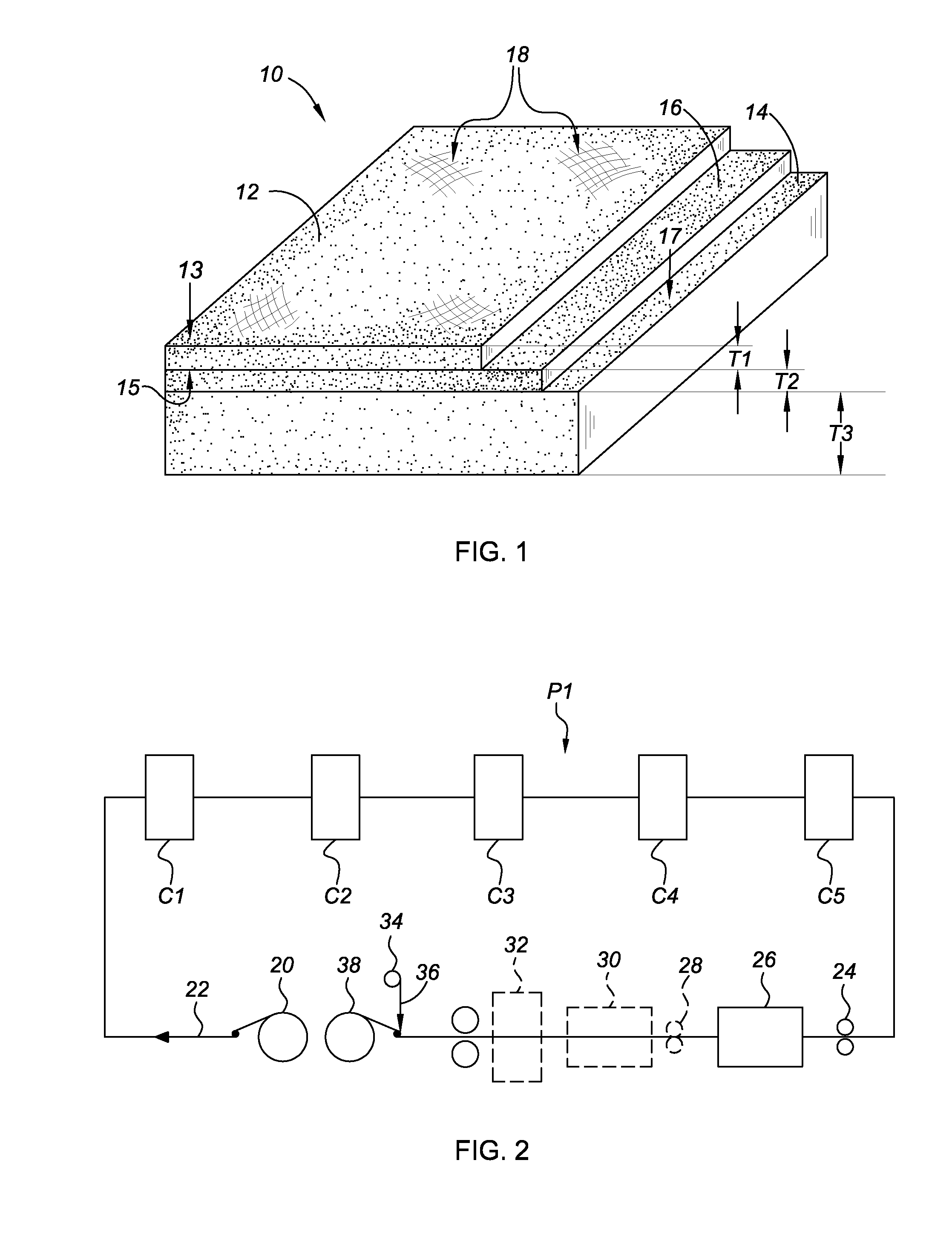
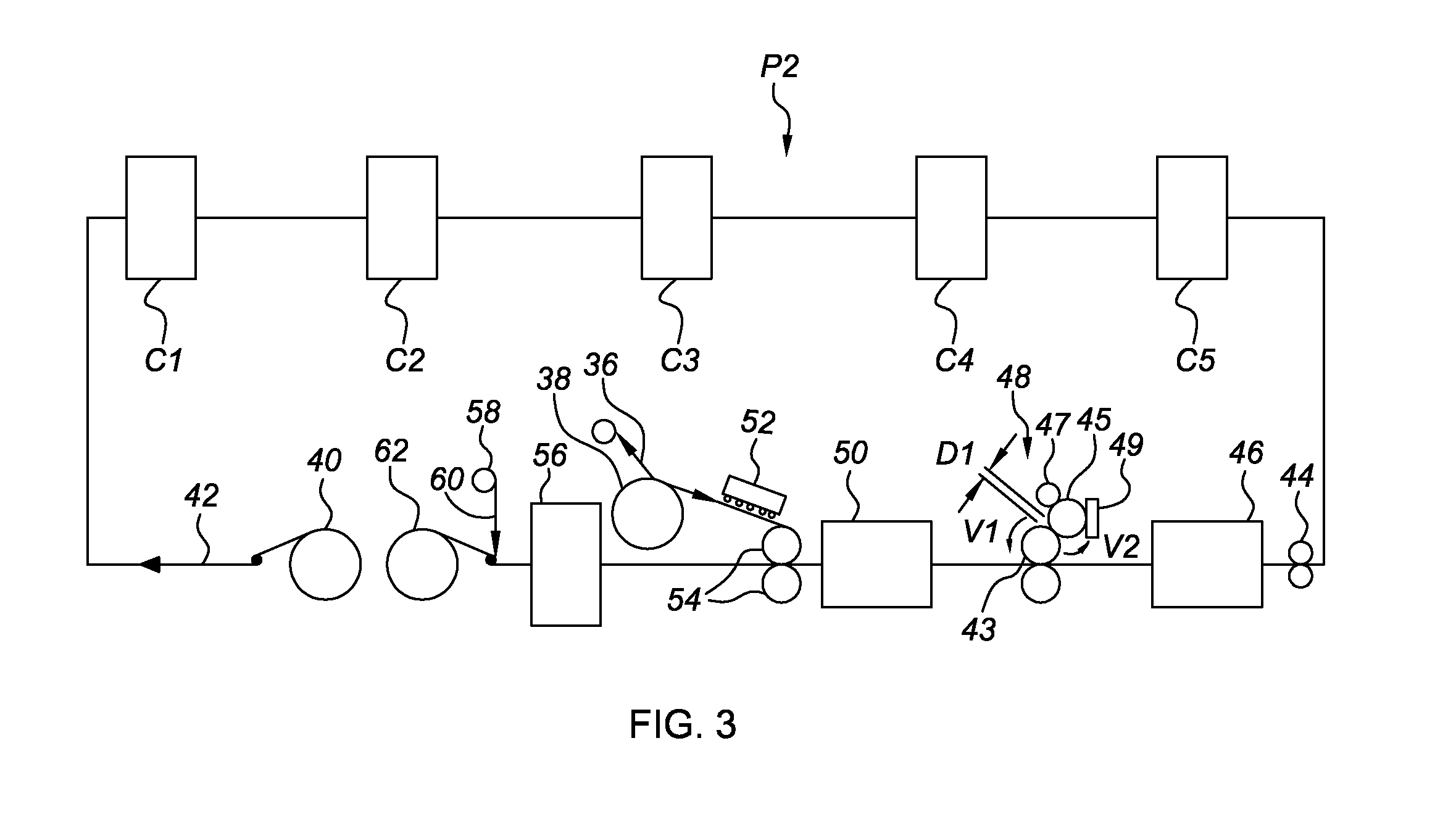
[0020]Referring to the drawings, wherein like reference numbers refer to like components throughout the several views, FIG. 1 schematically illustrates a decorative bimetal laminate structure, identified generally at 10 and referred to hereinafter as “laminate structure”, that is fabricated in accordance with the methods of the present invention. The embodiments of the present invention will be described herein with respect to the structure illustrated in FIG. 1 and the arrangement represented in FIGS. 2-3. It should be readily understood that the present invention is by no means limited to the exemplary applications presented in FIGS. 1-3. In addition, the drawings presented herein are not to scale and are provided purely for explanatory purposes. Thus, the specific and relative dimensions shown in the drawings are not to be considered limiting.

[0021]The laminate structure 10 of FIG. 1 includes an outer, decorative metallic layer 12 with an inner, metallic substrate layer 14 in opp...


PUM

PropertyMeasurementUnit
Thicknessaaaaaaaaaa
Thicknessaaaaaaaaaa
Pressureaaaaaaaaaa

Abstract

The present invention provides a bimetal laminate structure and improved method for manufacturing the same. The method includes: applying a layer of adhesive to a metallic substrate; and laminating a decorative metallic sheet to the metallic substrate in such a manner that substantially all surface defects and all read through appearance along an outer surface of the decorative metallic sheet are eliminated. The resultant bimetal laminate includes a decorative metallic layer consisting of a first metallic material, and a metallic substrate consisting of a second metallic material that is different from the first metallic material. The metal substrate has a thickness that is greater than the thickness of the decorative metallic layer. An adhesive layer is disposed between, and spans substantially the entirety of the decorative metallic layer and metallic substrate to rigidly attach the same.

Description

TECHNICAL FIELD[0001]The present invention relates generally to laminate structures, and more specifically to metal-polymer-metal laminates and methods of manufacturing the same.BACKGROUND OF THE INVENTION[0002]Decorative panels that can be painted or finished for aesthetic purposes are utilized in various industries for innumerable products. Many conventional home appliances, for example, have a number of external surfaces that are visible after installation which can consist of a decorative panel. Specifically, dishwashers, trash compactors, stoves, and most other kitchen appliance can have a decorative front surface.[0003]It is often desired that the decorative surface provide a “finished metallic look”. In addition to home appliances, decorative surfaces with a “finished metallic look” may be used for decorative metal faced building panels, metal faced sectional water tanks, and metal faced components for the automotive industry. However, the use of certain monolithic metal subs...

Claims


Application Information

Patent Timeline
IPC IPC(8): B32B7/12B65C9/25
CPCB32B7/12B32B15/01B32B15/08Y10T428/24967B32B2250/40Y10T428/2495B32B37/00B32B15/043B32B15/18B32B15/20B32B1/02B32B2255/06B32B2255/26B32B2255/28B32B2307/50B32B2307/718B32B2419/00B32B2439/00B32B2509/00B32B2605/08
Inventor ROELOFS, ROBERTBULLARD, DANBILOS, MIKETULLIS, BRYAN
Owner MATERIAL SCIENCES CORPORATION
Why Eureka
Try Eureka