

Coffee cup lid
- Summary
- Abstract
- Description
- Claims
- Application Information
AI Technical Summary
Benefits of technology
Problems solved by technology
Method used
Image

Examples
Example
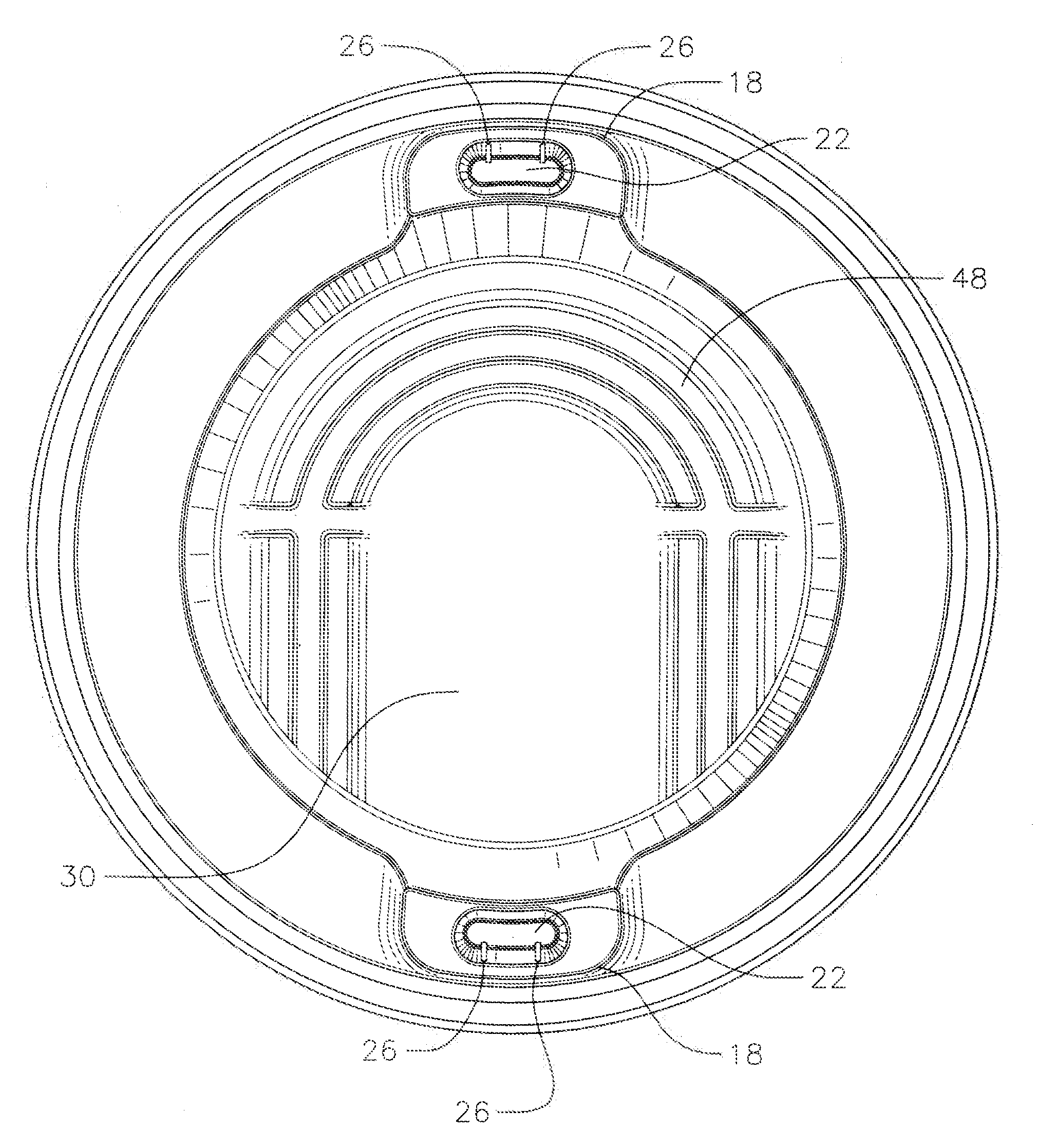
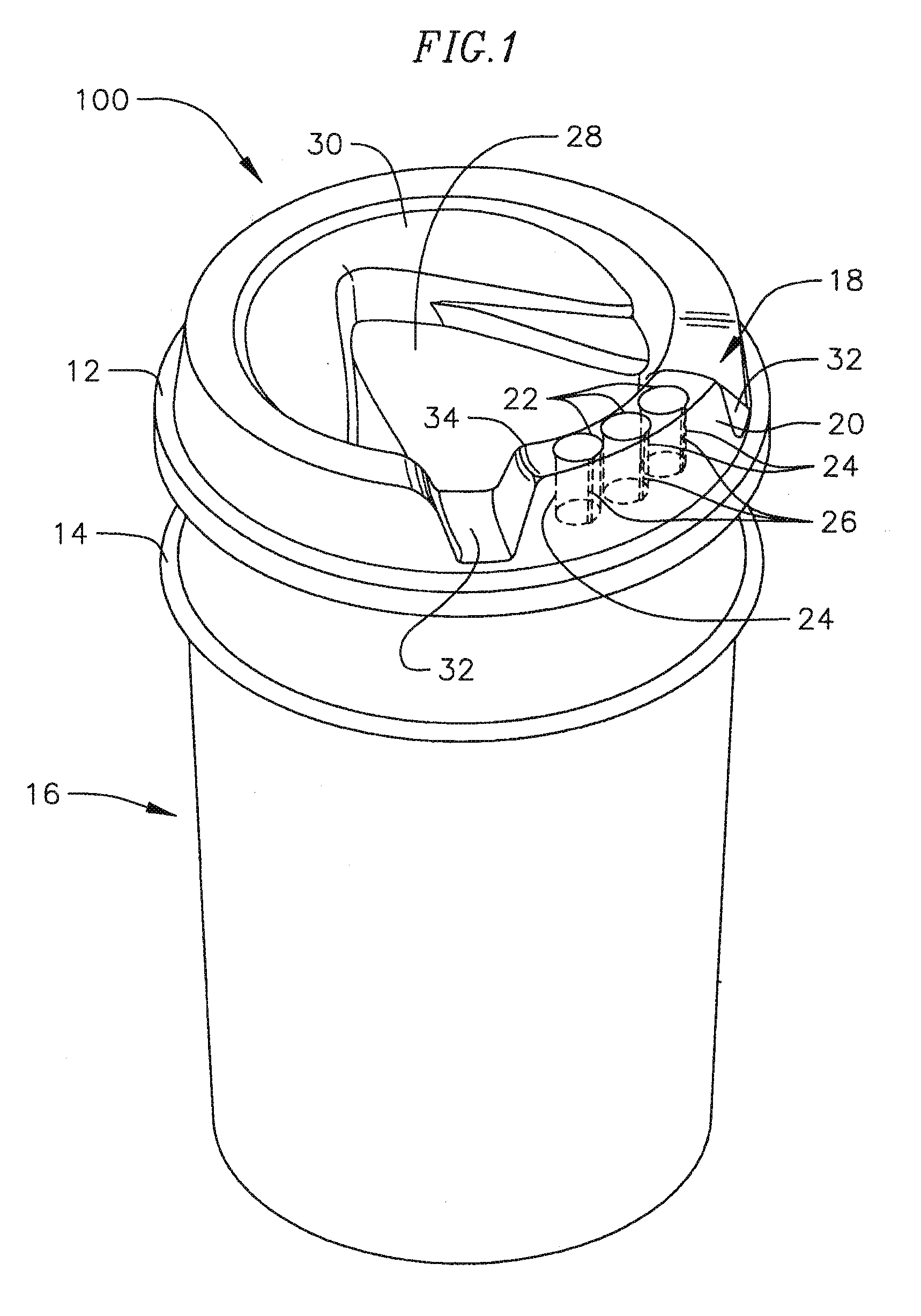
[0028]According to this first embodiment, the lid 100 further includes a recessed portion 28 in the top wall 30, to accommodate a user's nose, which might otherwise contact the top wall 30 when the combination of the lid 100 and cup 16 was tipped at a large angle. Further, the spout 18 is shaped to generally conform to a user's mouth, including recessed portions 32 and an inside wall 34 for the user's upper lip.
[0029]In combination with the rim 12, the spout 18 of the lid 100 according to the first exemplary embodiment is adapted to allow consumption of the beverage substantially as well as a simple hole would, but to reduce spills of the beverage out of the spout during transport. That is, the spout includes three openings 22 where the beverage exits the cup, but the openings generally do not provide a direct vertical path from the surface of the beverage outside the cup. In alternate embodiments, one, two, or essentially any number of openings could be used.
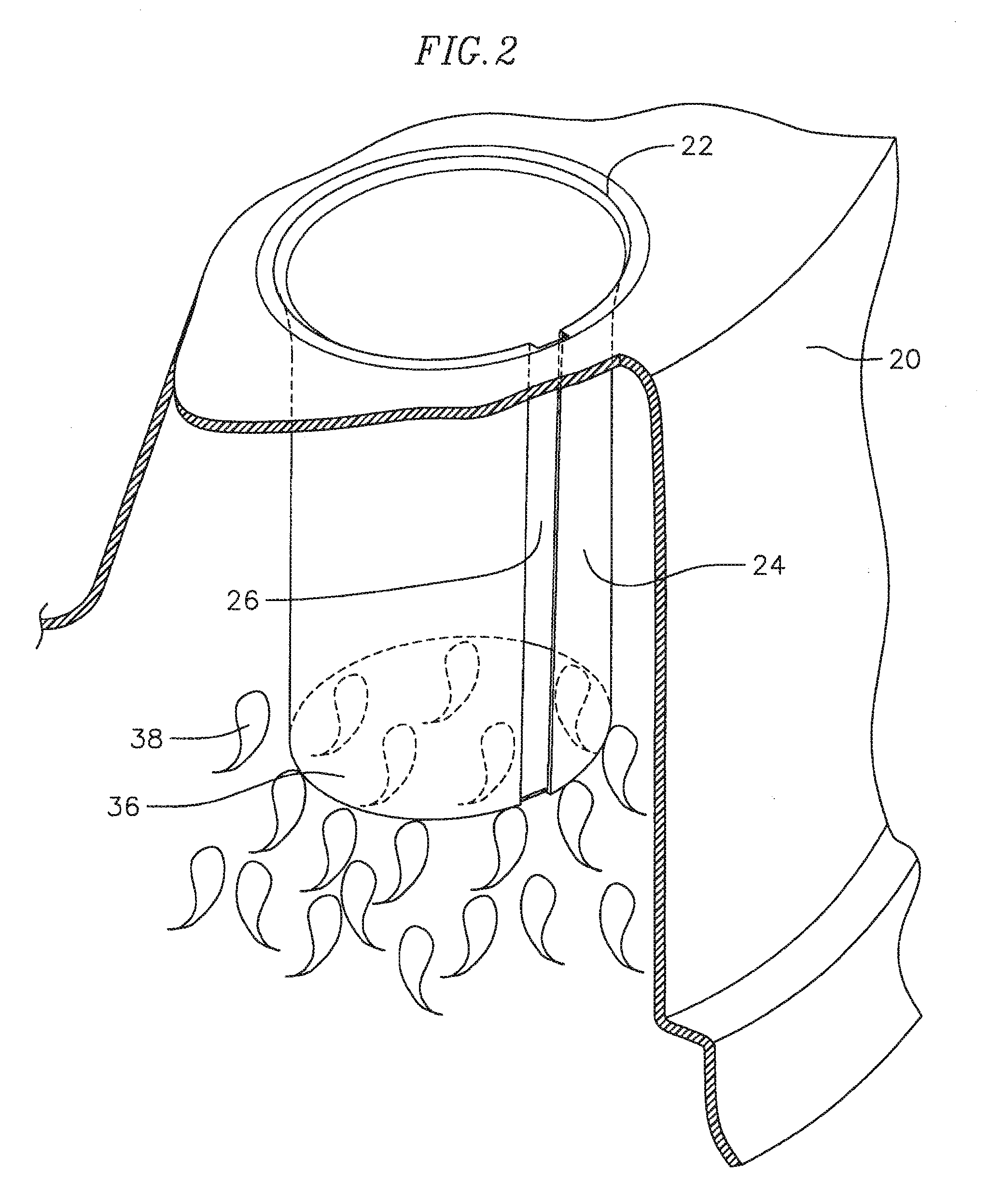
[0030]FIG. 2 is a detai...
PUM
 Abstract
Description
Claims
Application Information