
Ergonomic handle and articulating laparoscopic tool

a laparoscopic tool and ergonomic technology, applied in the field of ergonomic handle and articulating laparoscopic tool, can solve the problems of physician fatigue, difficult use of laparoscopic surgeon's tools, harm to highly trained physicians,

Active Publication Date: 2009-12-17
BOARD OF RGT UNIV OF NEBRASKA
View PDF56 Cites 14 Cited by
  • Summary
  • Abstract
  • Description
  • Claims
  • Application Information

AI Technical Summary

Benefits of technology

[0007]In one embodiment, the present invention relates to a laparoscopic apparatus. The apparatus comprises a handle having a body portion, a top surface, opposite bottom surface, a proximal and distal end and a shaft projecting from the distal end of the handle, the shaft having a proximal and distal end. The apparatus further comprises a control sphere located on the handle and an end effector located at the distal end of the shaft, wherein the end effector is connected to the control sphere such that movements made to the control sphere control movement of the end effector.
[0008]In another embodiment, the present invention relates to an ergonomic handle apparatus for use with a tool. The handle apparatus comprises a base having a body portion, a top surface, opposite bottom surface, a proximal and a distal end, where the top surface of the base being contoured to compliment the natural curve of the palm. The handle apparatus further comprises a control sphere located on the base, wherein the control sphere can be moved by one or more of a user's fingers to indicate direction and at least one lever projecting from the bottom surface, wherein the lever may be actuated by a user.
[0009]In yet another embodiment, the present invention relates to a laparoscopic apparatus. The apparatus comprises a handle having a body portion, a top surface, opposite bottom surface, a proximal and distal end, where the top surface of the base is contoured to compliment the natural curve of the palm. The apparatus further includes a shaft projecting from the distal end of the handle, the shaft having a proximal and distal end and a control sphere located on the handle. The control sphere can be moved by one or more of a user's fingers to indicate direction. An end effector is located at the distal end of the shaft and the end effector is connected to the control sphere such that movements made to the control sphere control movement of the end effector.

Problems solved by technology

The tools that laparoscopic surgeons must use are difficult to use and because of suboptimal design, they may actually be doing harm to the highly trained physician.
Additionally, poor laparoscopic tools increase physician fatigue, creating potential for errors that may harm the patient.
Current laparoscopic instruments have been found to be very poorly designed ergonomically and it is likely that ergonomics were not considered at all.
Some practicing laparoscopic surgeons frequently experience post operation pain or numbness.
Furthermore, four different handle designs used on laparoscopic tools (shank, pistol, axial, and ring handle) have been found to result in either painful pressure spots or caused extreme ulnar deviation.
Therefore, the tools available to perform the procedures are not yet perfected.
Limited work has been done by others to improve both the tools and procedures used in laparoscopy; however, an optimized tool, based on task analysis of laparoscopic surgery and sound ergonomic principles has not been prototyped and tested fully to date.

Method used


Image

  • Ergonomic handle and articulating laparoscopic tool
  • Ergonomic handle and articulating laparoscopic tool
  • Ergonomic handle and articulating laparoscopic tool

Examples


Embodiment Construction

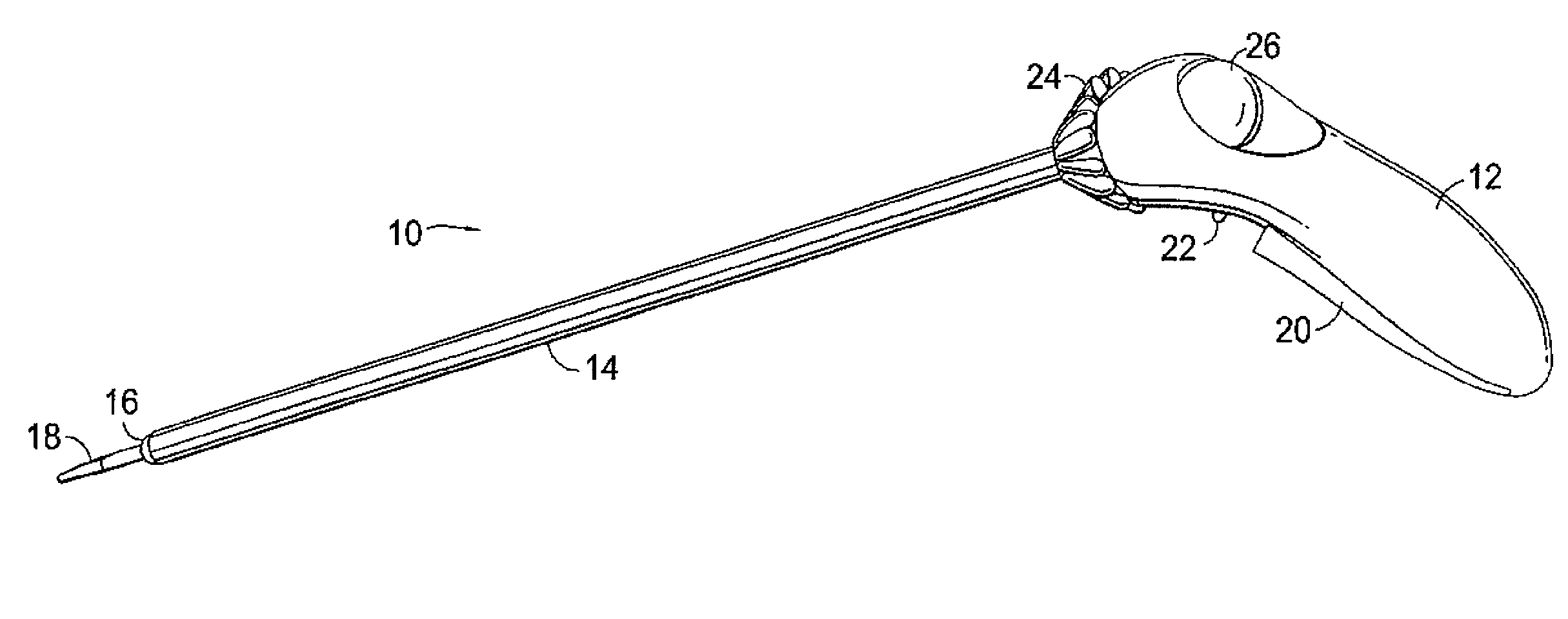
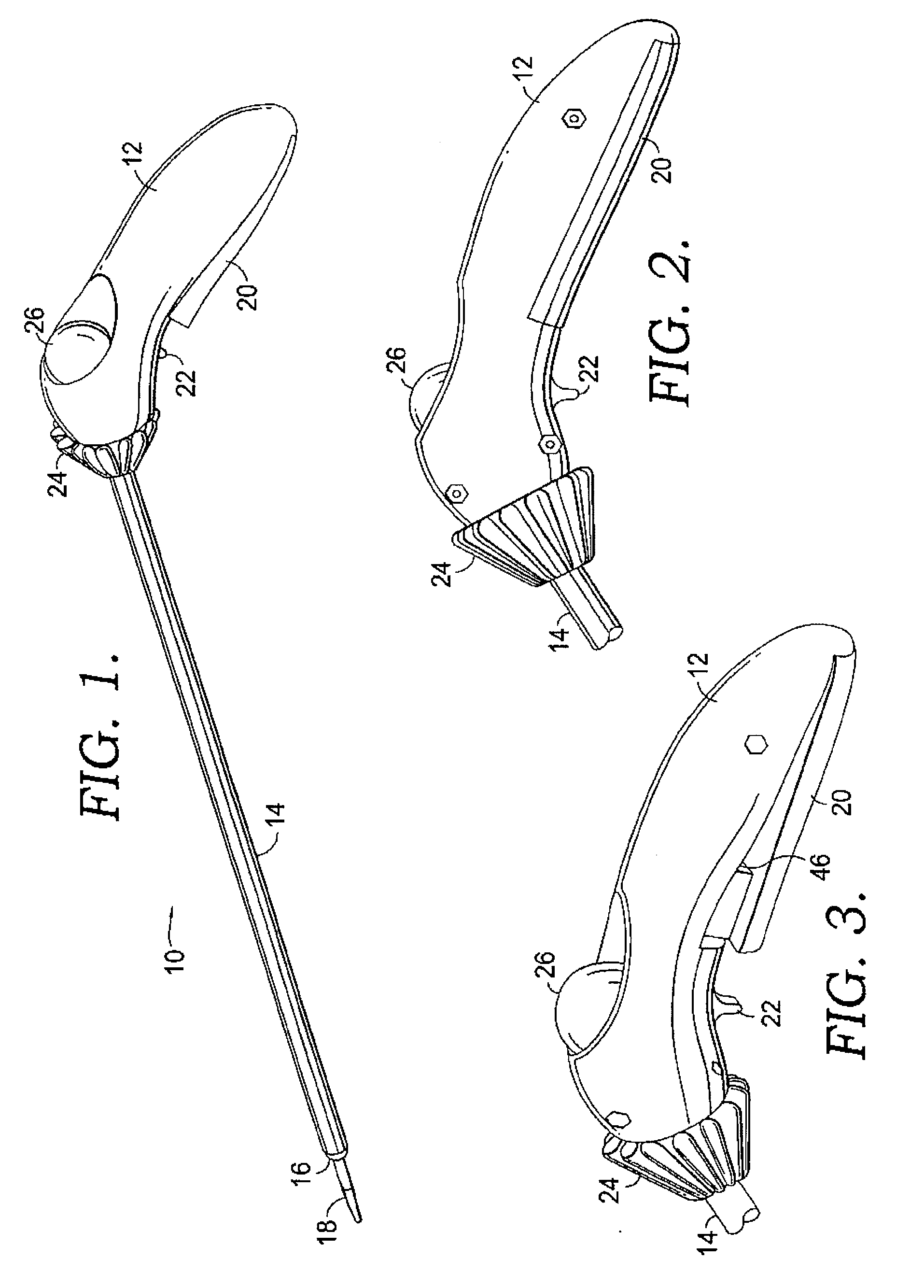
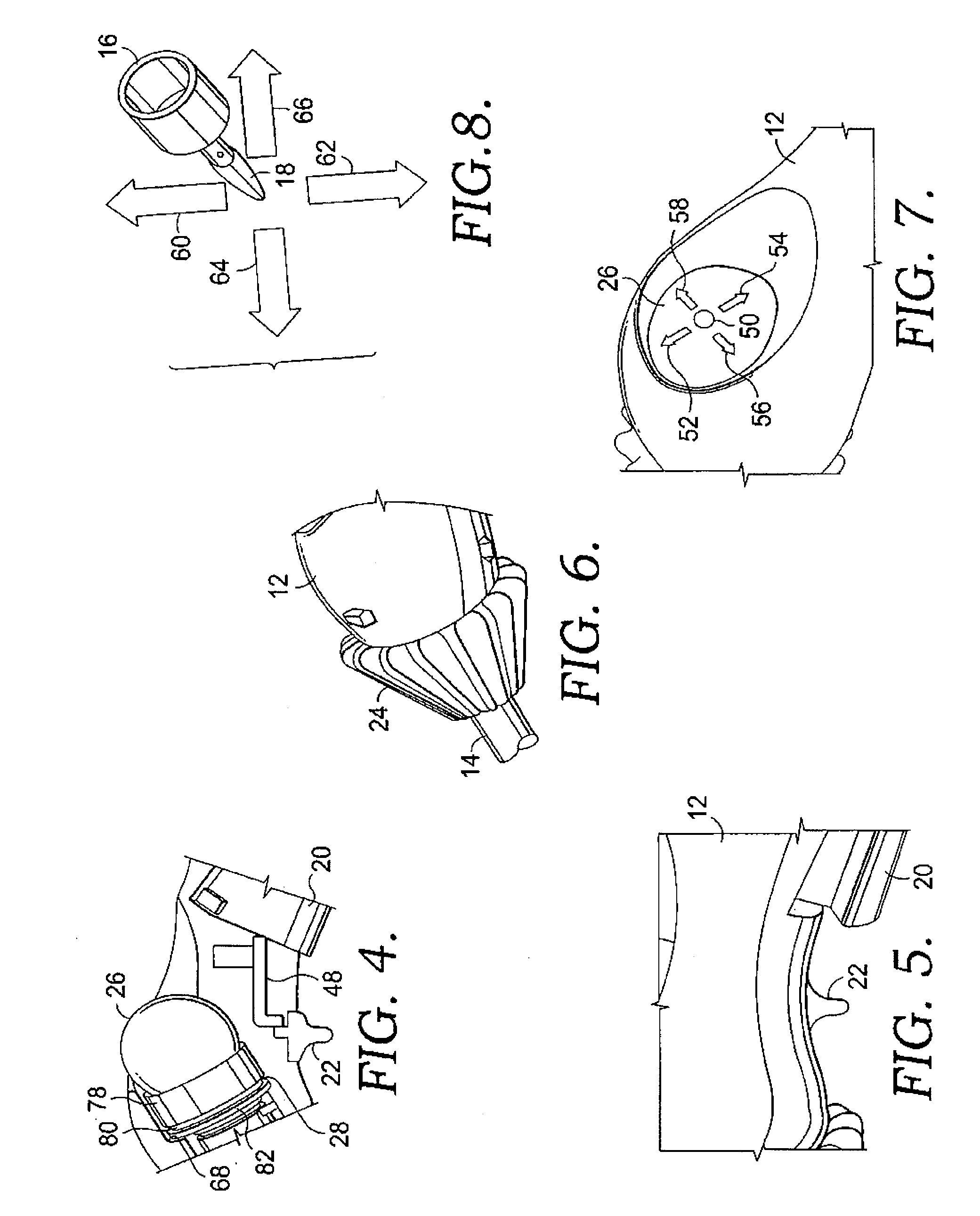
[0024]With reference to FIG. 1, an ergonomic laparoscopic tool (10) is shown. Laparoscopic tool (10) comprises of five main components: an ergonomic handle (12), several controls, a shaft (14), an articulating end effector (16), and graspers (18). The graspers (18) may be any effectors such as cutting forceps and jawed end effectors or may be powered for cauterizing. The cauterizing may include electrosurgical cutting and coagulation of tissue.

[0025]In one embodiment, the shaft (14) is a 10 mm shaft. In this embodiment, the shaft is about 10 mm in diameter and about 40 cm long. The shaft houses the wire guides and actuation cables, described later. However, one of skill in the art will appreciate that the shaft, wire guides and actuation cables are scalable and may be any size, including, but not limited to, about 3 mm and about 5 mm in diameter and about 35-55 cm long.

[0026]With reference next to FIG. 2, the tool handle (12) is a smooth, contoured shape. It is designed ergonomicall...


PUM


Abstract

The present invention relates to a laparoscopic apparatus. The apparatus comprises a handle having a body portion, a top surface, opposite bottom surface, a proximal and distal end. The top surface of the base is contoured to compliment the natural curve of the palm. The apparatus further includes a shaft projecting from the distal end of the handle. The shaft has a proximal and distal end. A control sphere is located on the handle. The control sphere can be moved by one or more of a user's fingers to indicate direction. An end effector is located at the distal end of the shaft. The end effector is connected to the control sphere such that movements made to the control sphere control cause movement (articulation) of the end effector.

Description

CROSS REFERENCE TO RELATED APPLICATIONS[0001]This application claims the benefit of priority under 35 U.S.C. §120 to U.S. application Ser. No. 11 / 056,021 filed Feb. 11, 2005, which claims the benefit of priority to U.S. Provisional Application No. 60 / 544,286 filed on Feb. 12, 2004, both of which are hereby incorporated by reference in their entirety.STATEMENT REGARDING FEDERALLY SPONSORED RESEARCH OR DEVELOPMENT[0002]Not applicable.BACKGROUND[0003]Surgeons have identified and studies have shown, laparoscopic techniques require greater concentration and place greater mental and physical stress on surgeons than open surgery. The tools that laparoscopic surgeons must use are difficult to use and because of suboptimal design, they may actually be doing harm to the highly trained physician. Additionally, poor laparoscopic tools increase physician fatigue, creating potential for errors that may harm the patient.[0004]Specialized instruments are required for laparoscopic surgery due to the...

Claims


Application Information

Patent Timeline
Patent Type & Authority Applications(United States)
IPC IPC(8): A61B1/00A61B17/28
CPCA61B17/29A61B17/2909A61B2017/2947A61B2017/2912A61B2017/2927A61B2017/2902
Inventor HALLBECK, M. SUSANOLEYNIKOV, DMITRYDONE, KATHRYNJUDKINS, TIMDIMARTINO, ALLISONMORSE, JONATHANVERNER, LAWTON N.
Owner BOARD OF RGT UNIV OF NEBRASKA
Learn More