Wiring topology for a building with a wireless network

a wireless network and wiring topology technology, applied in the field of wiring topology, can solve the problems of loss of income for owners, developers and realtors, inconvenient and costly, and the largest cost to a new owner is the cost of moving, so as to achieve the effect of reducing the amount of wiring

Inactive Publication Date: 2009-12-24
LUTRON TECH CO LLC +1
View PDF16 Cites 281 Cited by
  • Summary
  • Abstract
  • Description
  • Claims
  • Application Information

AI Technical Summary

Benefits of technology

[0005]The aforementioned problems are overcome by the present invention wherein the wiring topology of a building minimizes the amount of wiring and provides wireless control of the devices. The wiring topology for a building may be designed irrespective of the desired zones. That is, the number of desired zones need not be a factor in determining the number of home-run power lines or the number of circuit breakers.
[0006]These and other objects, advantages, and features of the invention will be more fully understood and appreciated by reference to the description of the current embodiment and the drawings.

Problems solved by technology

Downtime between tenants in buildings is a leading cause of lost income for owners, developers and realtors.
One of the largest costs to a new owner is the cost associated with moves, adds and changes to the wiring of the building in order to accommodate these different uses.
Changing which devices are controlled by a breaker requires physically rewiring the device, which is often inconvenient and costly.
However, these solutions do nothing to optimize the wiring topology of the building, which is cost inefficient.

Method used


Image

  • Wiring topology for a building with a wireless network
  • Wiring topology for a building with a wireless network
  • Wiring topology for a building with a wireless network

Examples


Embodiment Construction

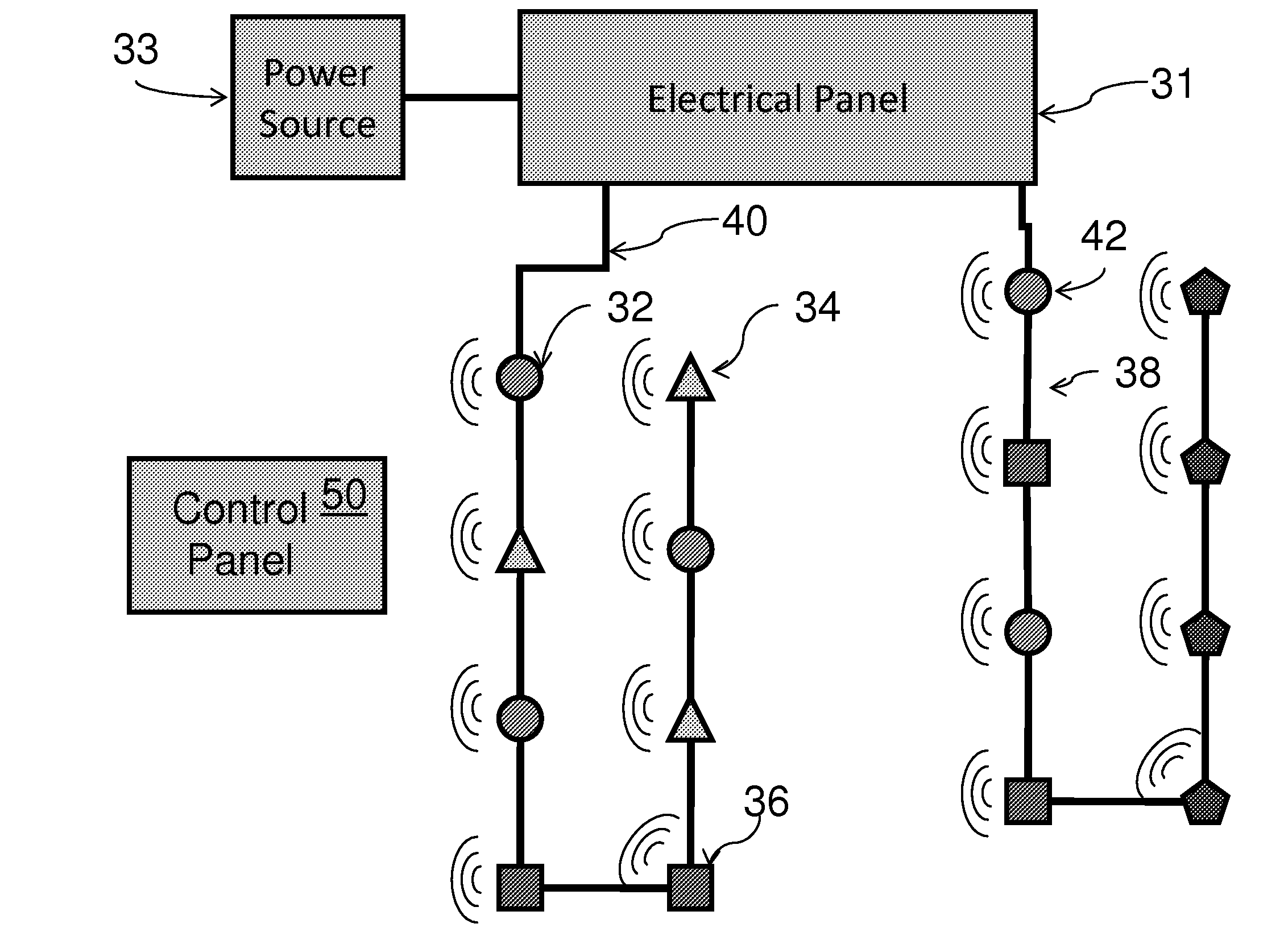
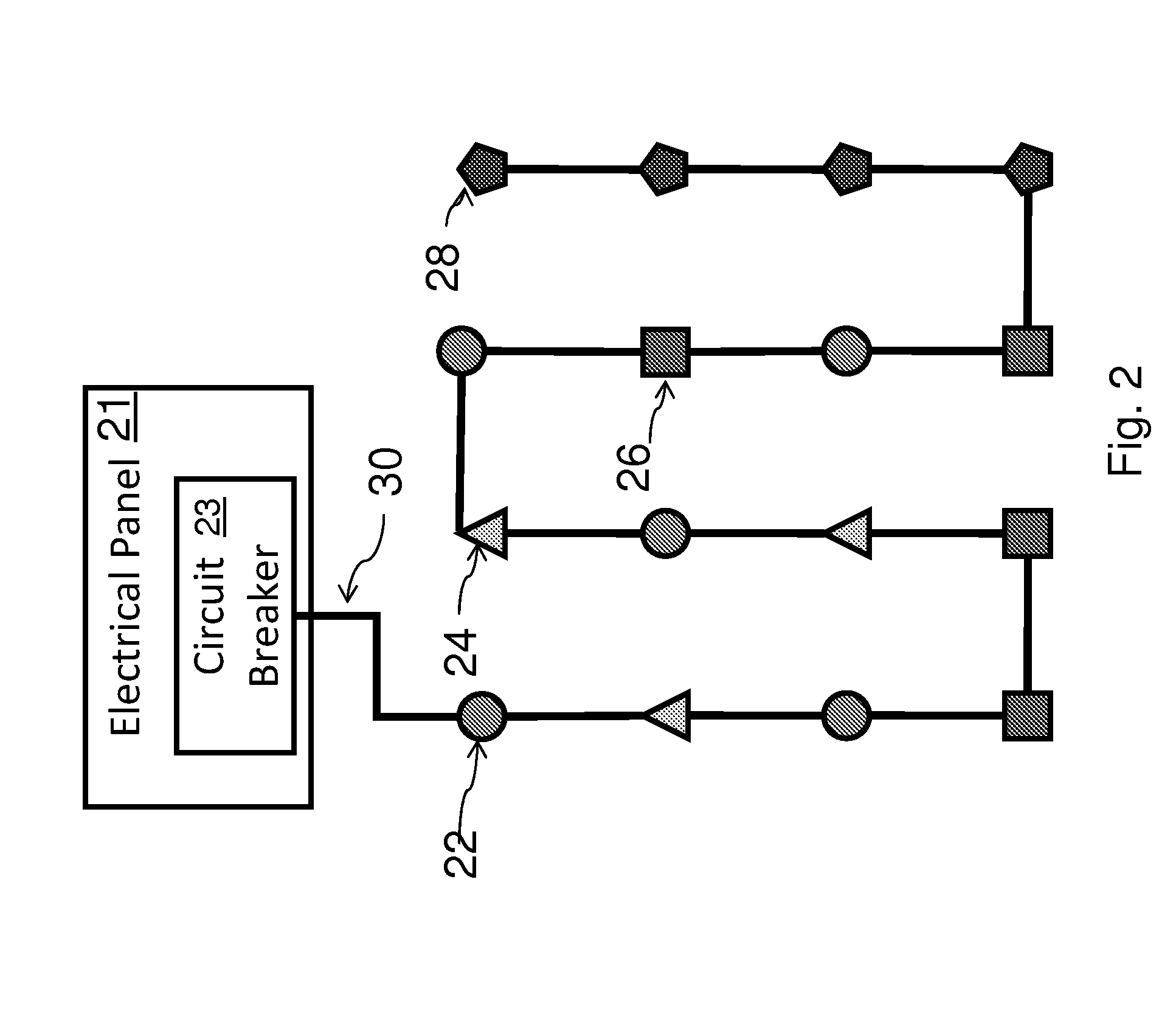
[0016]A power and control system in accordance with an embodiment of the present invention is shown in FIG. 2. The power and control system includes an electrical panel 21, a plurality of nodes 22, 24, 26, 28, and a home-run 30. In the illustrated embodiment, the nodes 22, 24, 26, 28 are wired in series with a single home-run in order to minimize the amount of wiring in the power and control system. In other embodiments, the nodes 22, 24, 26, 28 may be wired differently to minimize the amount of wiring and may include additional home-runs to the extent they are necessary to accommodate the load. As will be described in more detail later, each of the nodes may be controlled wirelessly. Wireless control allows nodes to be in different zones despite being connected to the same home-run power line to the electrical panel. This wiring topology in combination with wireless node control provides cost efficiency, reliability, and flexibility that is generally unattainable with traditional p...


PUM


Abstract

A power and control system for minimizing home-run power lines to fixtures located throughout a building and wirelessly controlling fixtures according to zones defined irrespective of their wiring. Less “pipe and box” is necessary when branch circuits are not used to define zones. A building may be wired in order to minimize costs, while increasing flexibility and reliability by implementing wireless zone control.

Description

BACKGROUND OF THE INVENTION[0001]The present invention relates to wiring topology, and more particularly to improvements in wiring topology such that wiring is more cost efficient, but maintains reliability and flexibility.[0002]Downtime between tenants in buildings is a leading cause of lost income for owners, developers and realtors. As buildings change hands, often they are rearranged for different uses. One of the largest costs to a new owner is the cost associated with moves, adds and changes to the wiring of the building in order to accommodate these different uses.[0003]Many buildings are wired using home-run wiring topology, as shown in FIG. 1. That is, multiple home-run power lines 10, 12, 14, 16 span from an electrical panel 1 to various devices 2, 4, 6, 8 in the building. The wiring is configured such that all devices connected to the same home-run are controlled by the same breaker and constitute one zone. Changing which devices are controlled by a breaker requires physi...

Claims


Application Information

Patent Timeline
Patent Type & Authority Applications(United States)
IPC IPC(8): G05B23/02
CPCH05B37/02Y02B60/50H05B37/0272H05B47/10H05B47/19
Inventor LEETE, III, LAWRENCE F.DOMAN, THOMAS J.KLEM, R. CRAIG
Owner LUTRON TECH CO LLC
Why Eureka
Try Eureka