Array powered solar tracking system

a solar tracking and array technology, applied in the field of solar tracking systems, can solve the problems of increasing the installation cost, time and complexity of mounting or burying power lines, limited power consumed for moving the tracking array, etc., and achieves the effect of reducing the amount of wiring required, minimizing the amount of wiring needed, and minimizing the amount of wiring

Inactive Publication Date: 2017-03-30
SOLARCITY
View PDF5 Cites 32 Cited by
  • Summary
  • Abstract
  • Description
  • Claims
  • Application Information

AI Technical Summary

Benefits of technology

[0010]In many aspects, the present disclosure is advantageous for a solar tracking array system in that the amount of wiring required for powering and operating components of the solar tracking array system are reduced. Such wiring can be copper-based, aluminum-based, or the like. Solar power sites, particularly industrial-scale solar power sites, can cover a large area, up to greater than five hundred acres. The provision of electrical power directly at each drive motor of a given tracking array from the connected PV modules of that tracking array significantly minimizes the wiring required to connect the tracking arrays to one or more power substations, a centralized power source, or grid power. Several advantages can be had by minimizing the amount of wiring needed between tracking arrays at a solar power site. For example, the amount of electricity lost due to the resistance of wiring can be significantly reduced. Also, the cost and labor involved in laying down wiring, or burying wiring in trenches, is reduced, which carries the further advantage of reducing the amount of wiring exposed to the elements or at risk of damage. In addition, tracking is not dependent on grid power, thus the tracking procedure avoids issues regarding grid failure.

Problems solved by technology

Moreover, power consumed for moving the tracking array is limited to the duration of time needed for a discrete movement of a torque tube, so any relative drain on the energy produced by a given tracker array is insignificant.
Mounting or burying these power lines adds an extra layer of cost, time, and complexity to the installation, in particular in areas where the ground is rocky or unstable.
Over the expected twenty to thirty year life of the array, those components are subject to failure from years of dissipating heat.
This will create additional maintenance costs that will erode the array owner's return on investment.

Method used


Image

  • Array powered solar tracking system
  • Array powered solar tracking system
  • Array powered solar tracking system

Examples


Embodiment Construction

[0018]Throughout this description for the purposes of explanation, numerous specific details are set forth in order to provide a thorough understanding of the many aspects and embodiments disclosed herein. It will be apparent, however, to one skilled in the art that the many aspects and embodiments may be practiced without some of these specific details. In other instances, known structures and devices are shown in diagram or schematic form to avoid obscuring the underlying principles of the described aspects and embodiments.

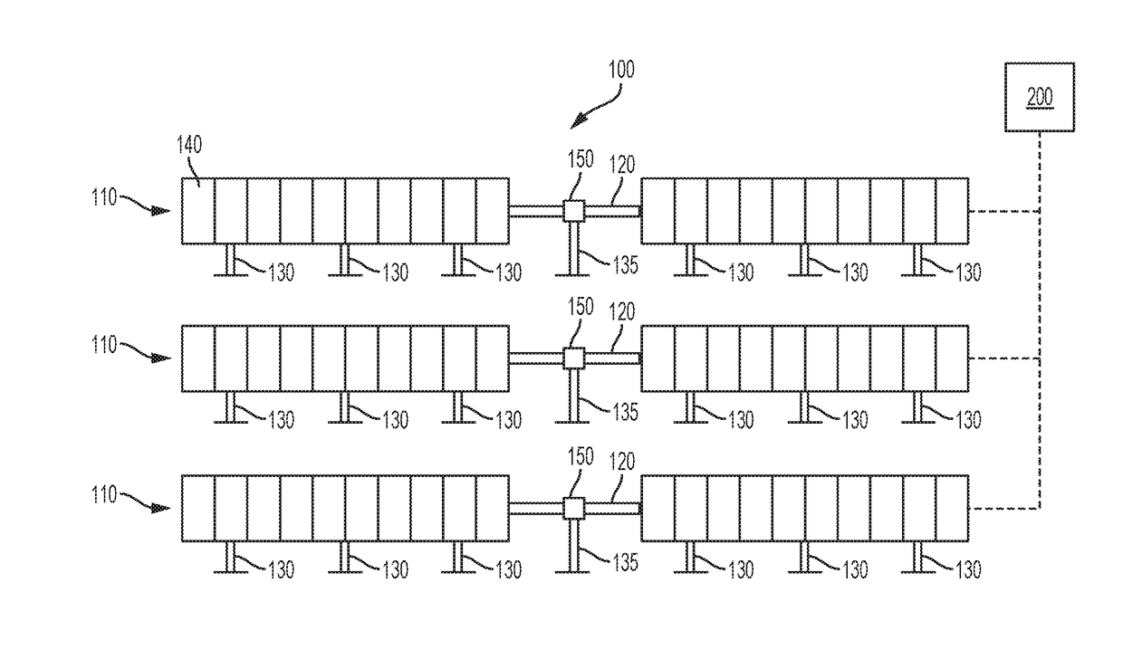
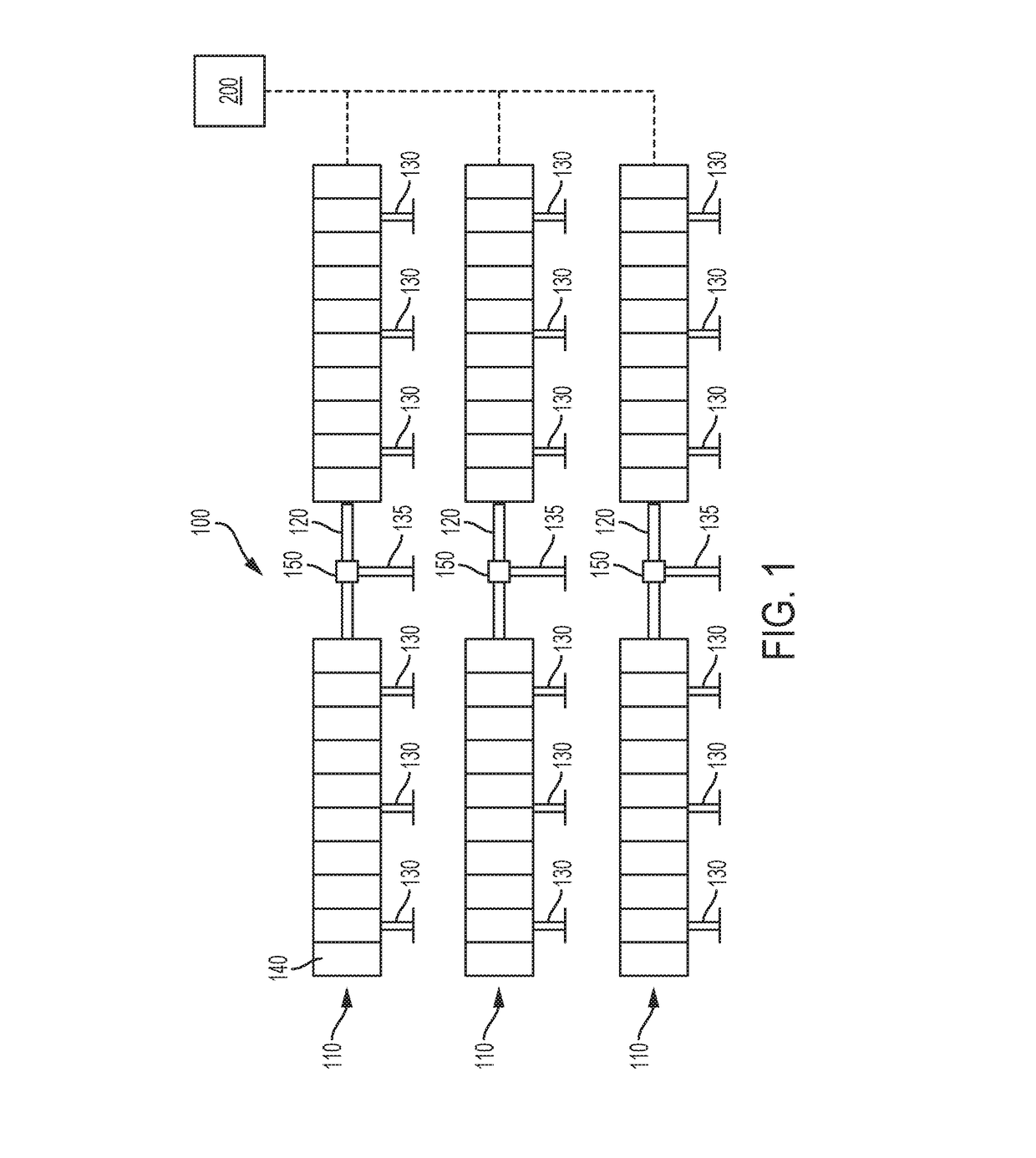
[0019]The present system provides for a self-powered, solar tracker array system designed to provide electrical power to a motor controlling the tracking motion of the array system, the power being diverted from the PV modules of the array system.

[0020]FIG. 1 is a schematic illustration of solar tracking array system 100. In particular, FIG. 1 shows solar tracking array system 100 having single-axis tracker arrays 110 according to various embodiments of the inve...


PUM


Abstract

A self-powered solar tracker array system and related method, where a torque tube supporting a plurality of strings of photovoltaic (PV) modules, a DC drive motor with a motor controller circuit, and a drive assembly is capable to rotate the torque tube with torque generated by the drive motor, where the power for operating the drive motor is taken from electricity generated by the PV modules. The system can include a battery to provide a power source for rotating the torque tubes when the PV modules are not generating electricity.

Description

CROSS-REFERENCE TO RELATED APPLICATION[0001]This claims the benefit of U.S. Provisional Patent Application No. 62 / 233,974 (Attorney Docket Number P184-1PUS), entitled “ARRAY POWERED SOLAR TRACKING SYSTEM,” filed on Sep. 28, 2015, which is herein incorporated by reference in its entirety.TECHNICAL FIELD[0002]The present disclosure relates to solar tracking systems, and in particular, to systems for powering a single-axis solar tracker without the need for separate grid power.BACKGROUND OF THE INVENTION[0003]Solar trackers are used to rotate photovoltaic (PV) modules to keep them perpendicular to the direct rays of the sun. Keeping the PV modules, as part of an array, at this orientation increases or optimizes the amount of energy that can be generated by the array, because energy generated by the array drops off with the cosine of the angle of incidence of solar rays on the surface of the array. Although trackers add an additional cost per watt over fixed ground-mount systems, the co...

Claims


Application Information

Patent Timeline
Patent Type & Authority Applications(United States)
IPC IPC(8): H02S20/32H02S40/38H02S40/30
CPCH02S20/32H02S40/38H02S40/30Y02E10/47F24S40/85F24S30/425Y02E10/50Y02E70/30
Inventor JENSEN, SOREN
Owner SOLARCITY
Why Eureka
Try Eureka