
Failure mode for HVAC system

a failure mode and hvac technology, applied in the field of hvac systems, can solve the problems of failure stage complete loss, conventional controllers are unaware of failure stages, and cannot achieve optimal control, so as to minimize the requirement, optimize the control over a wide range of system capacities, and achieve partial system capacity

Active Publication Date: 2007-05-08
CARRIER CORP
View PDF17 Cites 68 Cited by
  • Summary
  • Abstract
  • Description
  • Claims
  • Application Information

AI Technical Summary

Benefits of technology

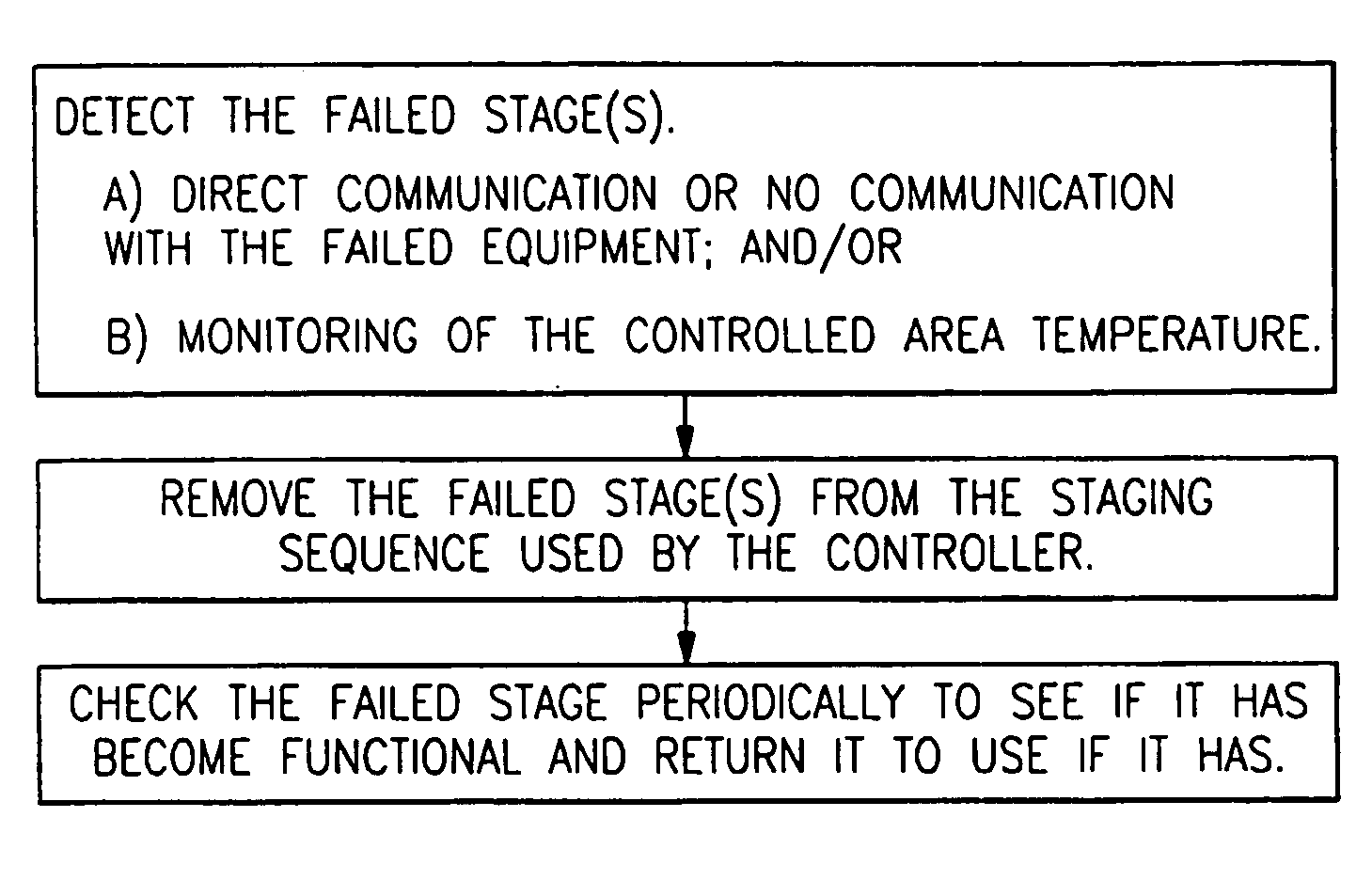
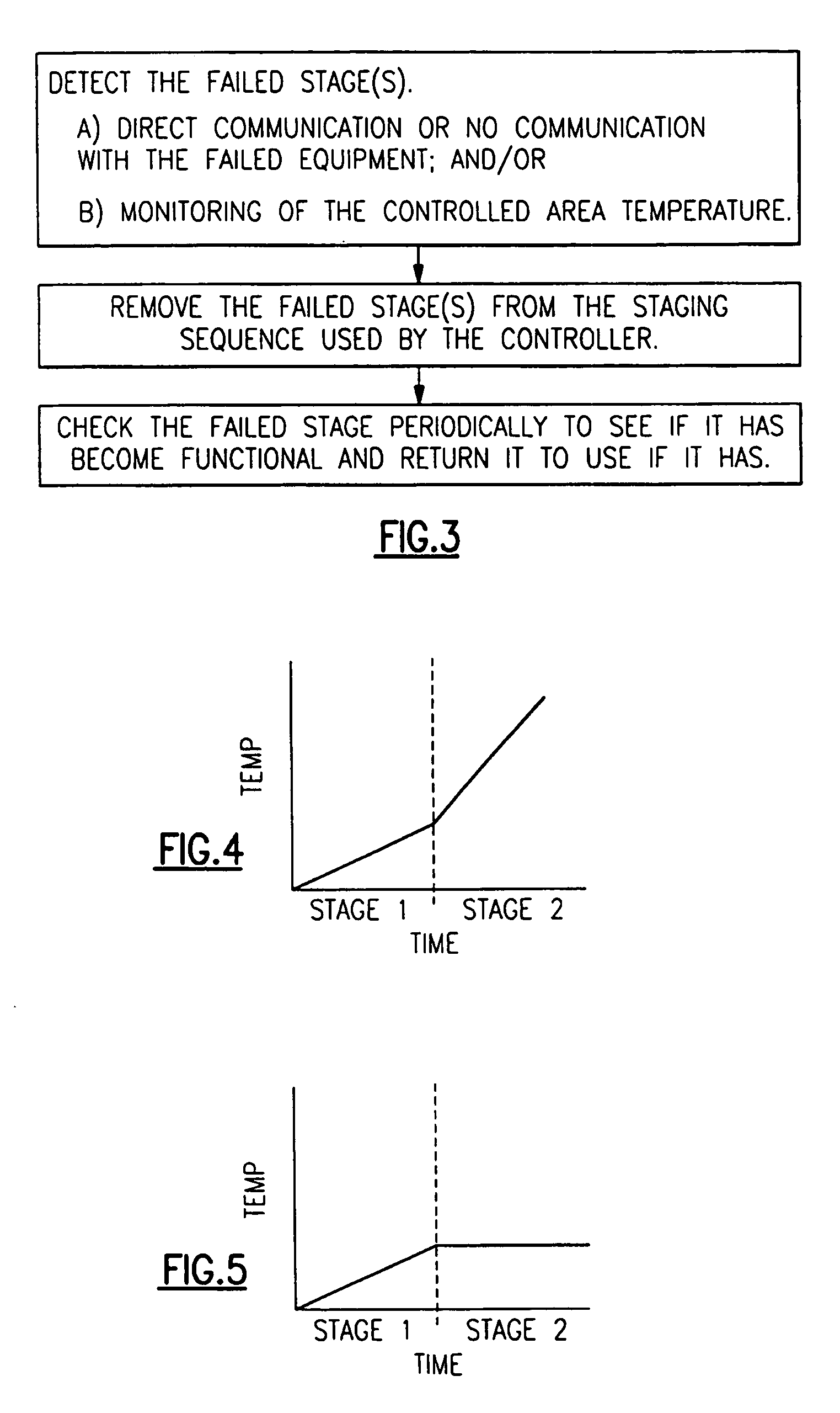
The present invention is an HVAC system control that can detect and isolate failed stages or components in the system. It can then remove them from the staging sequence and periodically check if they are functioning properly. This ensures that the system is always running at optimal capacity, minimizing delays in the staging sequence. The control system also learns the capacities of components and stages, incorporating this information into the control algorithm to optimize performance across a wide range of system capacities. Overall, the invention provides a more efficient and effective control system for HVAC systems.

Problems solved by technology

However, this may not be optimal as staging delays and temperature drop occur during the time in which the conventional component stages through the failed stage.
Moreover, conventional controllers are unaware of failed stages within the remote HVAC components.
The result may be complete loss of conditioning.

Method used


Image

  • Failure mode for HVAC system
  • Failure mode for HVAC system
  • Failure mode for HVAC system

Examples


Embodiment Construction

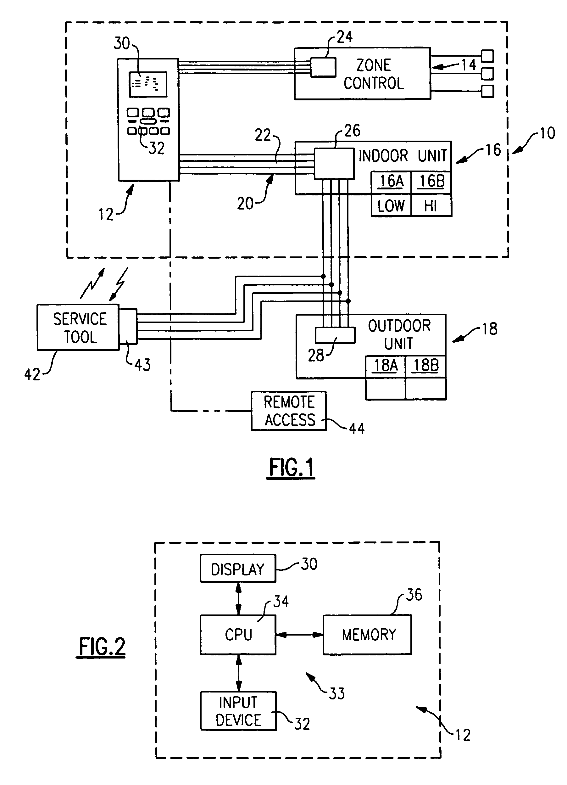
[0016]FIG. 1 illustrates a general schematic view of an HVAC system 10. The system 10 generally includes a central controller 12 that communicates with a zone control 14, an indoor unit 16, and an outdoor unit 18. The central controller 12 communicates over a digital communication bus 20. The bus 20 preferably includes four communication paths, such as four wires 22 or the like, which communicate data and power. It should be understood that other communication systems will likewise benefit from the present invention.

[0017]The zone control 14 preferably provides thermostat controls for each of several zones and a damper control for dampers associated with each of the zones as generally understood.

[0018]The zone control 14 includes a microprocessor controller 24 that communicates with the central controller 12 over the bus 20.

[0019]The indoor unit 16 includes an indoor unit microprocessor controller 26, which communicates with the central controller 12 over the bus 20. The indoor unit...


PUM


Abstract

A HVAC system provides a central control which detects failed stage(s); removes the failed stage(s) from the staging sequence used by the controller; and later checks the failed stage periodically to see if the failed stage has become functional so that the no properly operational stage is returned to a staging sequence. The central control detects the failed stages and / or components by direct communication with the failed stages and / or components and / or by monitoring a temperature of a controlled area to determine if any particular stage is operating properly.

Description

[0001]The present application claims priority to U.S. Provisional Patent Application Ser. No. 60 / 537,694, filed 20 Jan. 2004.BACKGROUND OF THE INVENTION[0002]The present invention relates to an HVAC system, and more particularly to bypassing a failed HVAC system component and / or stages to assure at least partial system capacity.[0003]A heating, ventilating, and air conditioning (HVAC) system includes multiple components that function together in a coordinated manner. Typically, an HVAC system includes an indoor unit such as a gas furnace or fan coil, an outdoor unit such as an A / C or heat pump, and a thermostat. More sophisticated systems may include a multi-zone control capacity with zone control and zone dampers. HVAC systems also frequently include subsystems such as filters, humidifiers, and ventilators.[0004]Typical HVAC systems include multiple stages of heating and / or cooling capacity. At the lowest demand, the first (lowest capacity) stage is activated. As demand increases p...

Claims


Application Information

Patent Timeline
Patent Type & Authority Patents(United States)
IPC IPC(8): G05B15/00G05B21/00G05B23/02
CPCG05B23/0291F24F11/006F24F11/0086F24F2011/0064F24F2011/0052F24F11/30F24F11/32F24F11/62F24F11/65F24F11/49F24F11/54F24F2110/10F24F11/38
Inventor VAN OSTRAND, WILLIAM F.SHAH, RAJENDRA K.
Owner CARRIER CORP
Learn More