Video data de-interlacing using perceptually-tuned interpolation scheme

a perceptual-tuned interpolation and video data technology, applied in the field of display devices, can solve the problems of inability to implement suitable algorithms on a single stb integrated circuit, the size of a motion window, and the inability of most sophisticated arbitration procedures to keep up with the volume of data, so as to minimize processing power, reduce the requirement of frame storage, and improve the quality of the de-interlacer

Inactive Publication Date: 2006-01-31
NEC ELECTRONICS INC
View PDF29 Cites 67 Cited by
  • Summary
  • Abstract
  • Description
  • Claims
  • Application Information

AI Technical Summary

Benefits of technology

[0016]In this disclosure, a de-interlacing method which minimizes the frame storage requirements is taught. The method also minimizes processing power associated with using motion estimation. Only a three field memory is needed for the method and one block-based motion estimation task is utilized. The quality of the de-interlacer is ensured by incorporating perceptual measures which are obtained from the image samples and assisted by the ME process.

Problems solved by technology

Such robustness depends on several conditions, each creating a major challenge in realizing a hardware unit which can be integrated in a single STB chip.
Due to the operating frequency and memory bandwidth of current STB integrated circuit, even the most sophisticated arbitration procedures can not keep up with the volume of the data.
Another challenge for ME techniques is the size of a motion window for which object displacement is to be obtained.
However, a suitable algorithm cannot be implemented on a single STB integrated circuit.
These boundary conditions impose a precision barrier on feature identification of pixels, and in particular the pixels neighboring the contours of the ROIs.
Other factors such as instrument noise, luminance or contrast changes, and special effects, challenge the accurate extractions of spatio-temporal features.

Method used


Image

  • Video data de-interlacing using perceptually-tuned interpolation scheme
  • Video data de-interlacing using perceptually-tuned interpolation scheme
  • Video data de-interlacing using perceptually-tuned interpolation scheme

Examples


Embodiment Construction

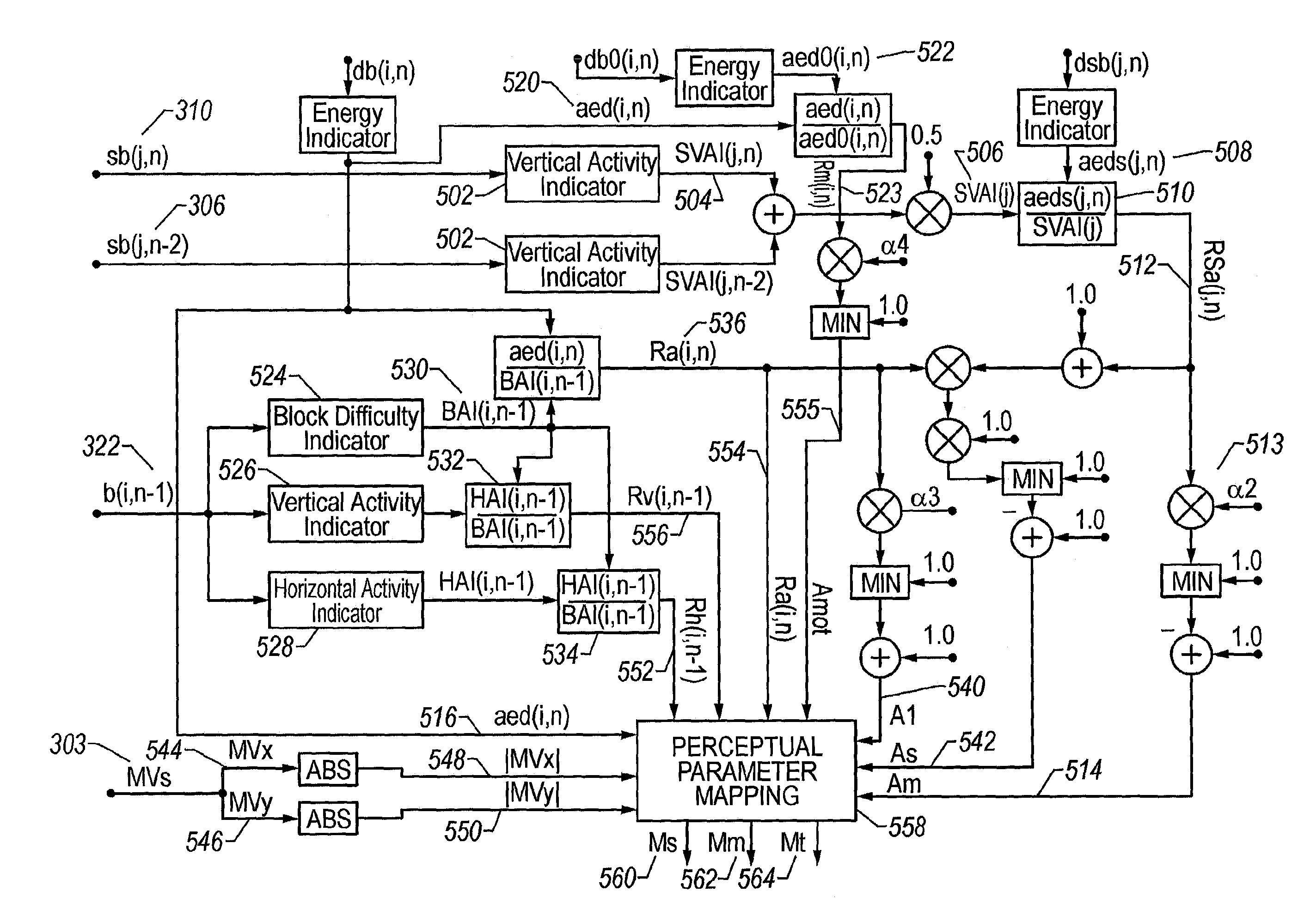
[0039]The following sets forth a detailed description of a mode for carrying out the invention. The description is intended to be illustrative of the invention and should not be taken to be limiting. A de-interlacing architecture is taught. The de-interlacing architecture adopts a perceptual model to measure membership probabilities for a collection of image samples of an interlaced video source with respect to extracted static, motion, and texture image components of the same collection. The probabilities are used to prioritize contributions from the three image components and produce a progressive video sequence which is a summation of the portions of the aforementioned components.

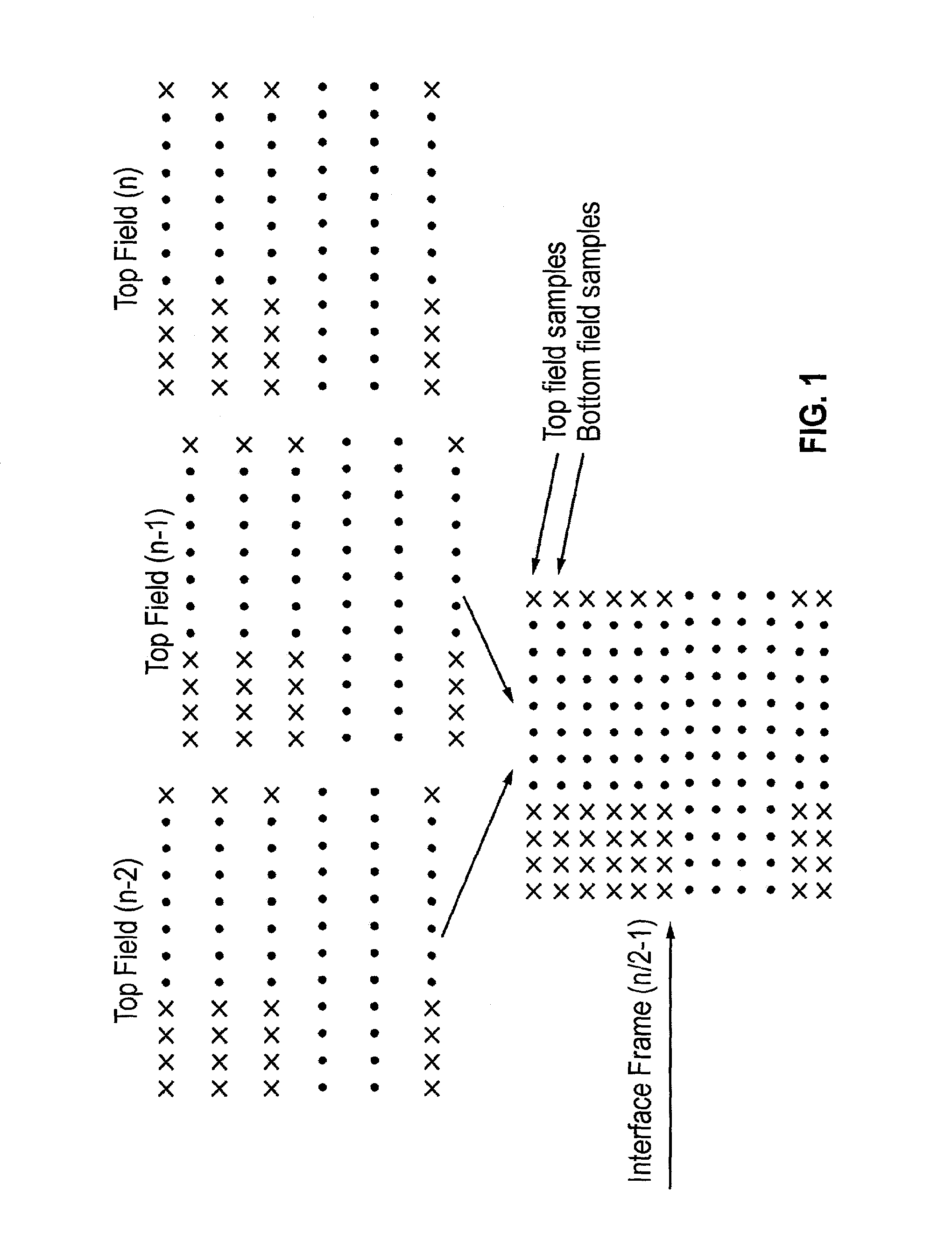
[0040]Consider field (n−1) which together with a field immediately in past or future would form an interlaced frame. Index (n−1) defines the temporal location of the field (n−1). In order to convert the scan rate of field (n−1) to a progressive scan rate, field (n−1) and two adjacent fields in past (fiel...


PUM


Abstract

A de-interlacing architecture is taught. The de-interlacing architecture adopts a perceptual model to measure membership probabilities for a collection of image samples of an interlaced video source with respect to extracted static, motion, and texture image components of the same collection. The probabilities are used to prioritize contributions from the three image components and produce a progressive video sequence which is a summation of the portions of the aforementioned components. The perceptual model uses a dual-stage motion-based image difficulty measuring scheme to equalize contributions from the three image components in a manner that video artifacts in the output signal are least perceptive. A parameter mapping technique composed of several logic units, a decision function, a weight assignment block, and a look-up table, will be presented to derive the final component weights. The mapping technique contains a multitude of thresholds and decisions which aid in interpolating the missing lines of the progressive frame.

Description

BACKGROUND OF THE INVENTION[0001]1. Field of the Invention[0002]This invention is generally related to display devices such as television monitors or liquid crystal displays, and more particularly to the field of video scan rate conversion from interlace to progressive format.[0003]2. Description of the Related Art[0004]Recent advances in digital televisions and flat-panel displays have greatly impacted the use of progressively scanned video formats. Video data are conventionally produced in the 2:1 interlaced scan rate for transmission and broadcast applications whereas the computer community uses the 1:1 progressive scan rate. The advantages of interlaced (I) video signals are that half the samples in a frame are updated in time, and therefore, half the bandwidth of the source is sufficient for data processing. On the other hand, progressive (P) scans display less flicker, are visually more pleasing, and are less stressful on human eye. Finally, progressive video materials are mor...

Claims


Application Information

Patent Timeline
Patent Type & Authority Patents(United States)
IPC IPC(8): H04N7/01H04N11/20H04N5/44
CPCH04N7/012
Inventor MOHSENIAN, NADER
Owner NEC ELECTRONICS INC
Why Eureka
Try Eureka