

Hearing aid with capacitive switch
- Summary
- Abstract
- Description
- Claims
- Application Information
AI Technical Summary
Benefits of technology
Problems solved by technology
Method used
Image

Examples
Embodiment Construction
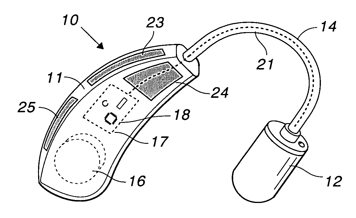
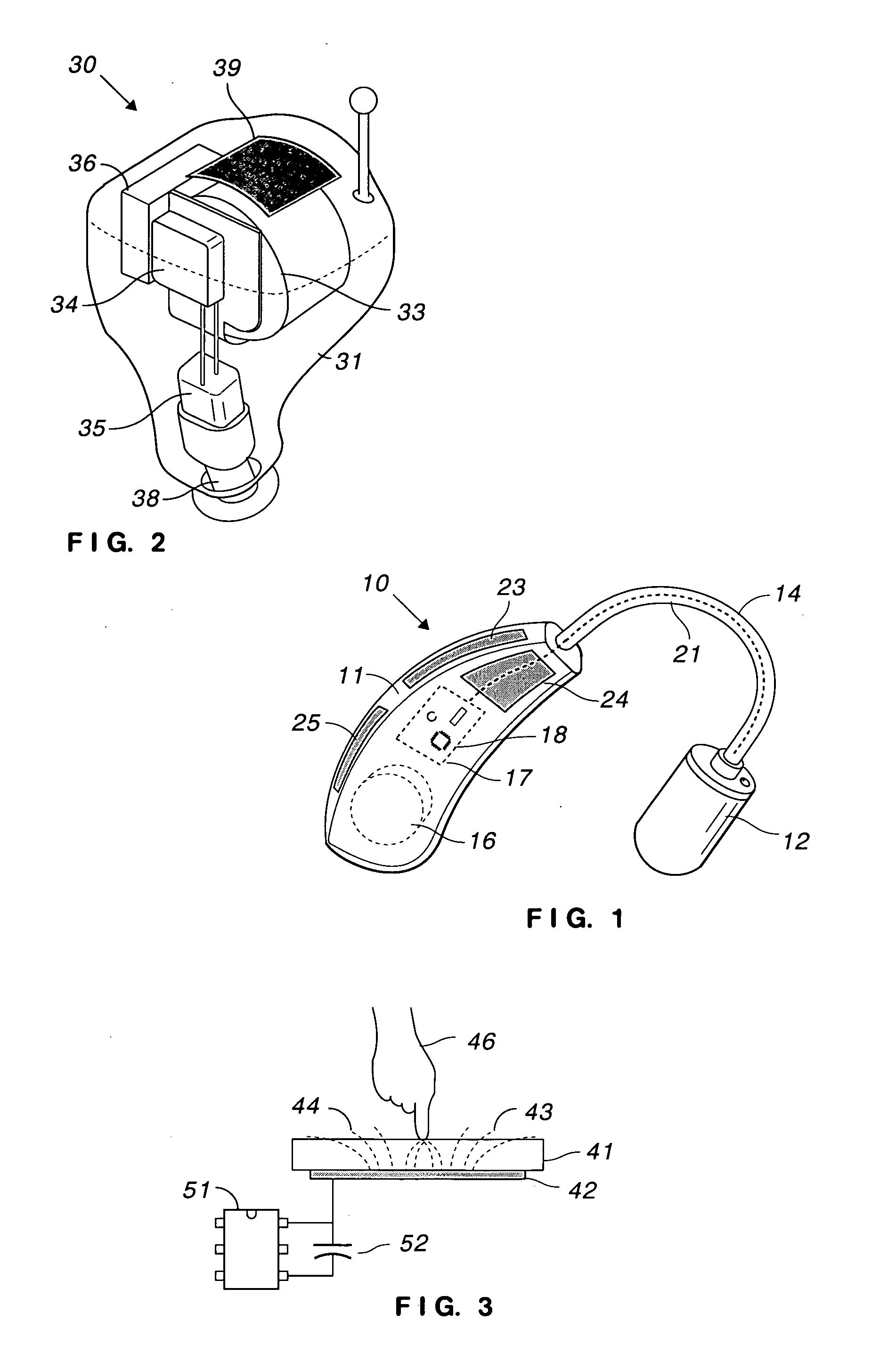
[0015]In FIG. 1, hearing aid 10 includes housing 11 coupled to earpiece 12 by cable 14. Within housing 11 are battery 16 and circuit board 17. Circuit board 17 includes programmed microprocessor 18 and other circuitry for processing audio signals, charging battery 16, and other functions. A speaker (not shown) is located in earpiece 12 and a microphone (not shown) is located in housing 11. The speaker is coupled to circuit board 17 by wires 21 in cable 14.
[0016]For historical reasons, a speaker is sometimes referred to as a “receiver” in the hearing aid art. That is not the terminology being used herein. A hearing aid has at least one speaker and at least one microphone.
[0017]In accordance with the invention, hearing aid 10 includes electrode 23 located underneath a portion of housing 11. Electrode 23 is electrically coupled to circuit board 17 and is a capacitive touch sensor. Electrode 23 is preferably located on the inside of the convex surface of a BTE hearing aid. Electrode 23 ...
PUM
 Abstract
Description
Claims
Application Information