
Devices and methods for fracture reduction

a technology of fracture reduction and devices, applied in the field of orthopedic devices to treat fractured bone, can solve the problems of severe medical complications, predisposing the bone to fracture, deformation, etc., and achieve the effect of improving facilitating the targeting of fractures

Active Publication Date: 2009-12-31
GLOBUS MEDICAL INC
View PDF127 Cites 123 Cited by
  • Summary
  • Abstract
  • Description
  • Claims
  • Application Information

AI Technical Summary

Benefits of technology

This patent describes new tools and techniques that can help healthcare professionals better diagnose and treat spine fractures. Specifically, it focuses on improving instruments used during vertebral plastic surgery (also known as kyphoplasty) which involves replacing damaged or collapsed parts of the spine with reinforced materials like bone cement. These innovations include specialized equipment such as curved drills and reamers that make it easier to locate and fix the fracture, while also allowing surgeons to form a cavity within the patient's body without causing excessive damage. Overall, this technology helps ensure safer and effective treatment outcomes for patients who require these procedures.

Problems solved by technology

The technical problem addressed in this patent is how to accurately target and reduce bone flaws caused by diseases like osteoporotic compression fracture or tumors in the spinal column without damaging surrounding structures. Current methods involve inserting a balloon tool into the bone but it can be difficult to determine where the cavity needs to be formed. There is a need for improved tools and procedures to better identify and locate these areas of damage before performing any necessary repairs.

Method used


Image

  • Devices and methods for fracture reduction
  • Devices and methods for fracture reduction
  • Devices and methods for fracture reduction

Examples


Embodiment Construction

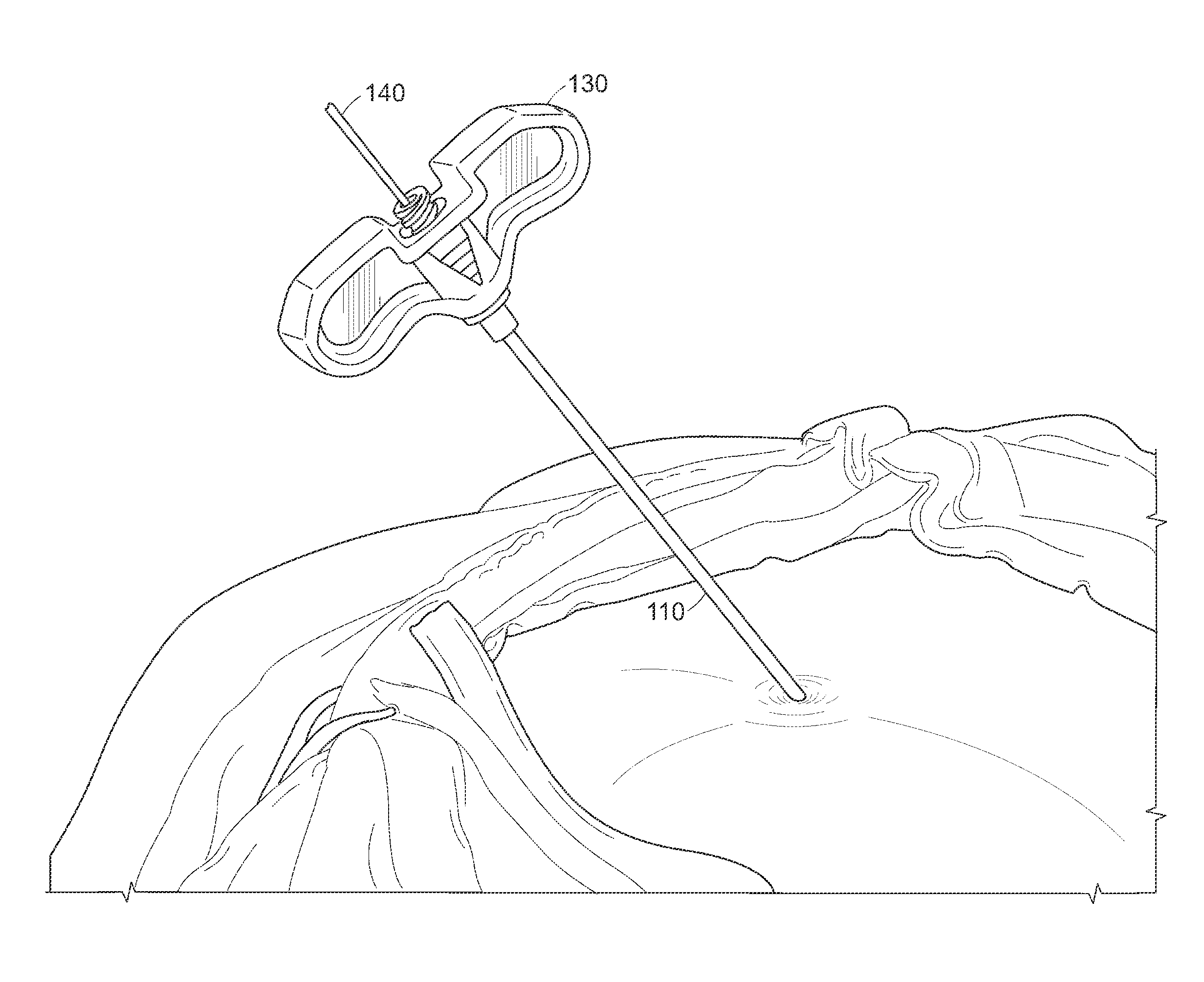
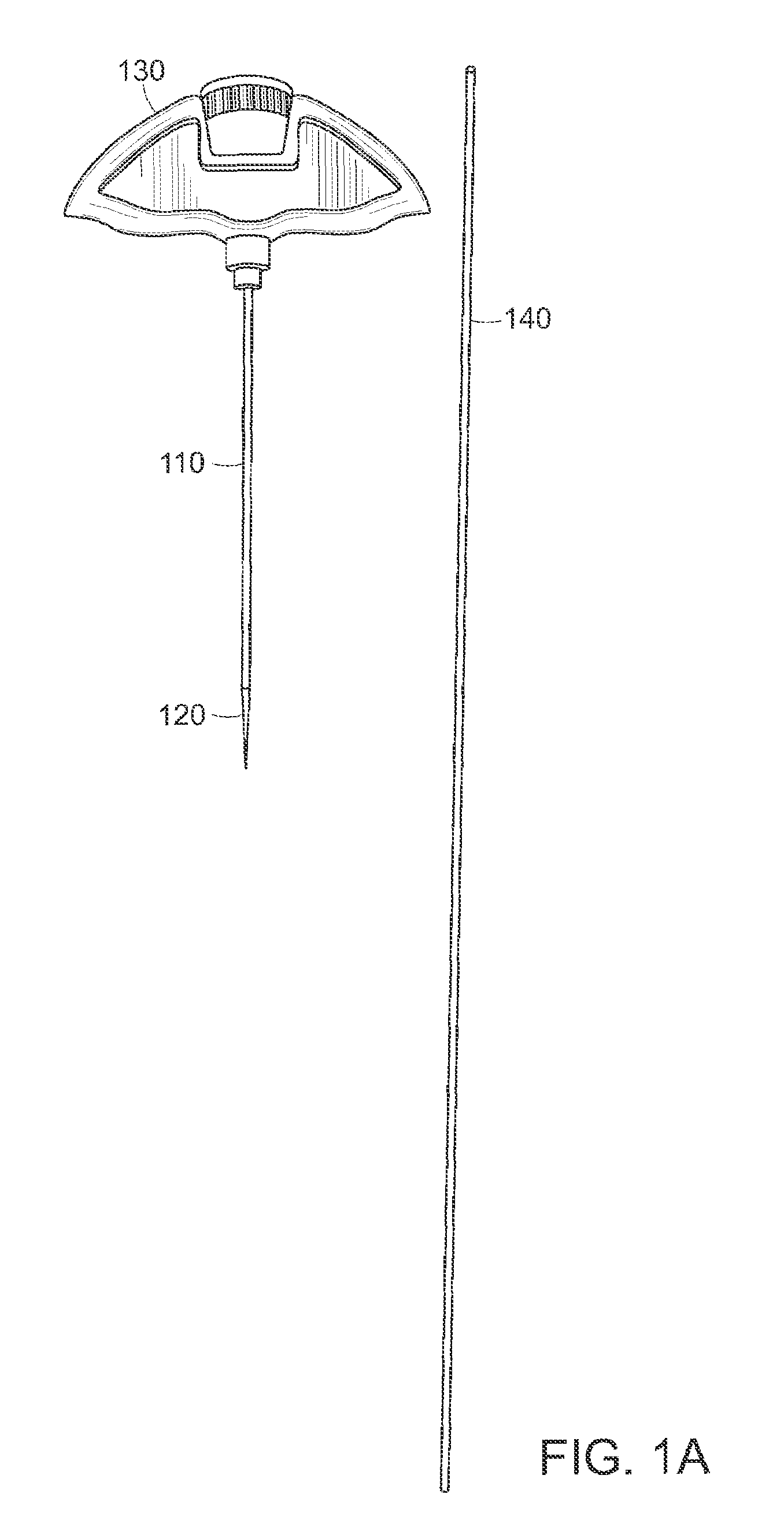
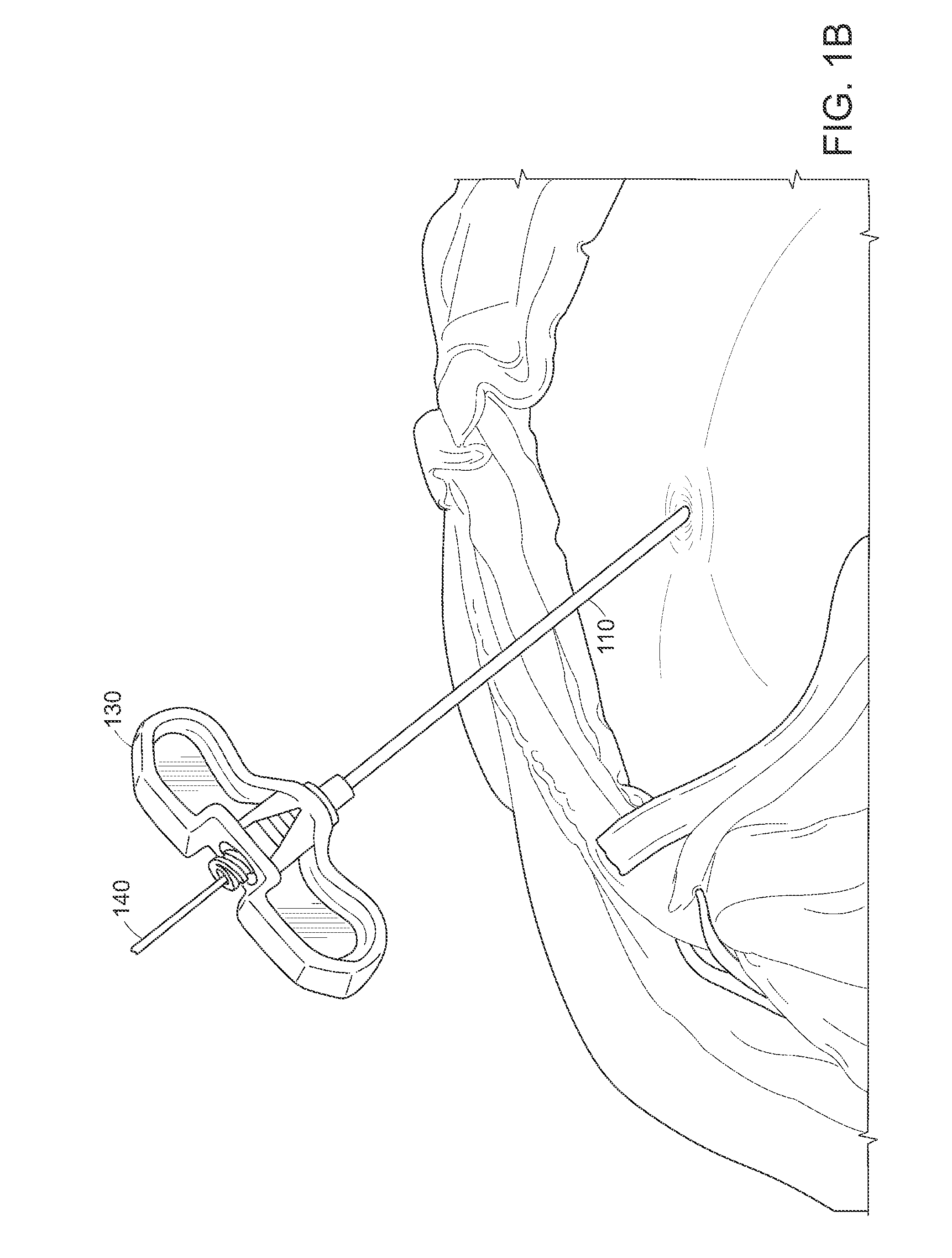
[0102]To maximize the effectiveness of balloon dilation within a fractured bone to cause distraction of the bone fragments, it may be beneficial to more effectively target the location within the bone prior to dilatation of the balloon. In the specific case of vertebral body fracture, there are anatomical challenges to targeting with minimally invasive instrumentation. Safe passage of instruments and balloon catheters from the posterior surgical approach is generally achieved through a straight cannula positioned either within the pedicle of the vertebral body or just lateral to the pedicle to avoid potentially dangerous penetration of the cannula in the spinal canal. This anatomically defined trajectory often does not align with, or target, the fracture within the vertebral body. Therefore, prior techniques are limited in their ability to effectively target the fracture.

[0103]Limitations in current balloon expanding techniques may be overcome through use of a drill device that curv...


PUM


Abstract

The invention relates to a method of creating a curvilinear cavity within a vertebral body or other bony structure. The invention also relates to devices that may be used to perform the steps to create the curvilinear cavity. In one embodiment, a method of forming a curvilinear void in bony structure may include the steps of accessing a bony structure with a cannula, inserting a distal end of a drill device through the cannula and into the bony structure, manipulating the distal end of the drill device to create a curvilinear void in the bony structure, enlarging the void by expansion of a balloon element mounted to the drill device, and deflating the balloon element and removing the drill device from the cannula.

Description


Claims


Application Information

Patent Timeline
Owner GLOBUS MEDICAL INC
Learn More