Breathable downhole fiber optic cable and a method of restoring performance

a fiber optic cable and fiber optic cable technology, applied in the field can solve the problems of increasing transmission loss, difficult if not impossible system use of fiber optic cables, and problems such as difficult to restore performan

Active Publication Date: 2010-01-14
AFL COMM LLC
View PDF7 Cites 14 Cited by
  • Summary
  • Abstract
  • Description
  • Claims
  • Application Information

AI Technical Summary

Benefits of technology

[0008]Exemplary embodiments of the present invention overcome the above disadvantages and other disadvantages not described above. Also, the present invention is not required to overcome the disadvantages described above, and an exemplary embodiment of the present invention may not overcome any of the problems described above. The present invention provides a fiber optic cable structure which can breathe or ventilate to reduce hydrogen partial pressure next to the core of the fiber and a method of restoring performance in a fiber optic cable.
[0014]According to another exemplary embodiment of the present invention, there is provided a method of restoring performance in a fiber optic cable, including providing a fiber optic cable having at least one path, extending through the length of the fiber optic cable, which provides a channel for a purge gas to flow for removing hydrogen gas from the fiber optic cable; and injecting a purge gas into the at least one path, wherein the hydrogen gas diffuses out of each of a plurality of optical fibers contained within the fiber optic cable.
[0019]The advantage of the proposed structure / system is that the optical fibers attenuation will not be permanently degraded in this structure. Although it may increase, the purge process will restore the performance.

Problems solved by technology

Fiber optic cables used for oil well applications where the cable is installed in the well have been problematic.
The presence of hydrogen in the fiber will create an increase in transmission loss.
This can make the systems that use the fiber—fiber optic pressure sensors and distributed temperature sensing—difficult if not impossible depending on the optical loss level in the fiber.
Due to these issues, the cable structures used will often use hydrogen getters of various sorts to consume the present hydrogen.
Unfortunately, some of the hydrogen getters are not suitable for temperatures above 150 C and at higher temperatures are suspected of actually releasing the hydrogen they have captured.
The use of a carbon layer has shown to lose its effectiveness as temperatures rise.
Unfortunately, although these options extend the life of the cable, these cable structures will show increased optical loss over time in the presence of hydrogen.
This is discussed in detail in “Development of Fibers Optic Cables for Permanent Geothermal Wellbore Deployment”, R. Normann, J Weiss and J. Krumhansl. The issue with this logic is that diffusion rates of hydrogen in a pure silica fiber or a doped fiber is the same, so in the presence of the same hydrogen concentration both fiber types will exhibit attenuation loss.
Thus, the problem of survivability of fiber optic downhole cables has been approached with the intent of extending the life of the cable by creating barriers for the hydrogen.

Method used


Image

  • Breathable downhole fiber optic cable and a method of restoring performance
  • Breathable downhole fiber optic cable and a method of restoring performance
  • Breathable downhole fiber optic cable and a method of restoring performance

Examples


Embodiment Construction

[0030]The matters defined in the description such as a detailed construction and elements are provided to assist in a comprehensive understanding of the embodiment of the invention and are merely exemplary. Accordingly, those of ordinary skill in the art will recognize that various changes and modifications of the embodiment described herein can be made without departing from the scope and spirit of the invention. Also, descriptions of well-known functions and constructions are omitted for clarity and conciseness.

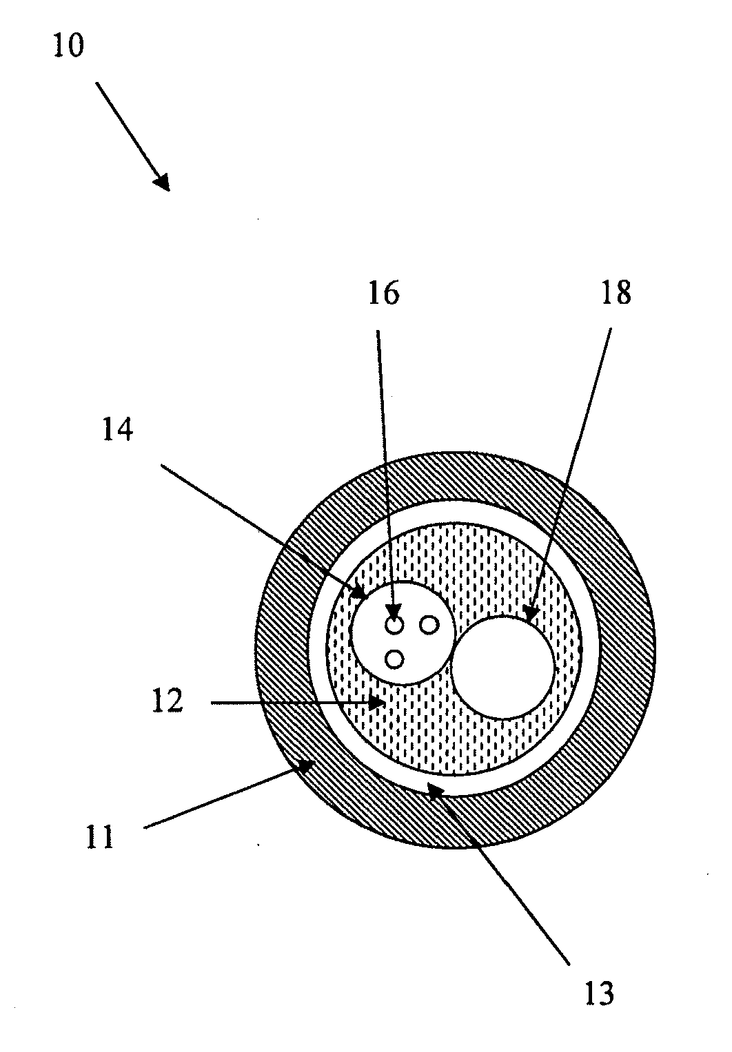
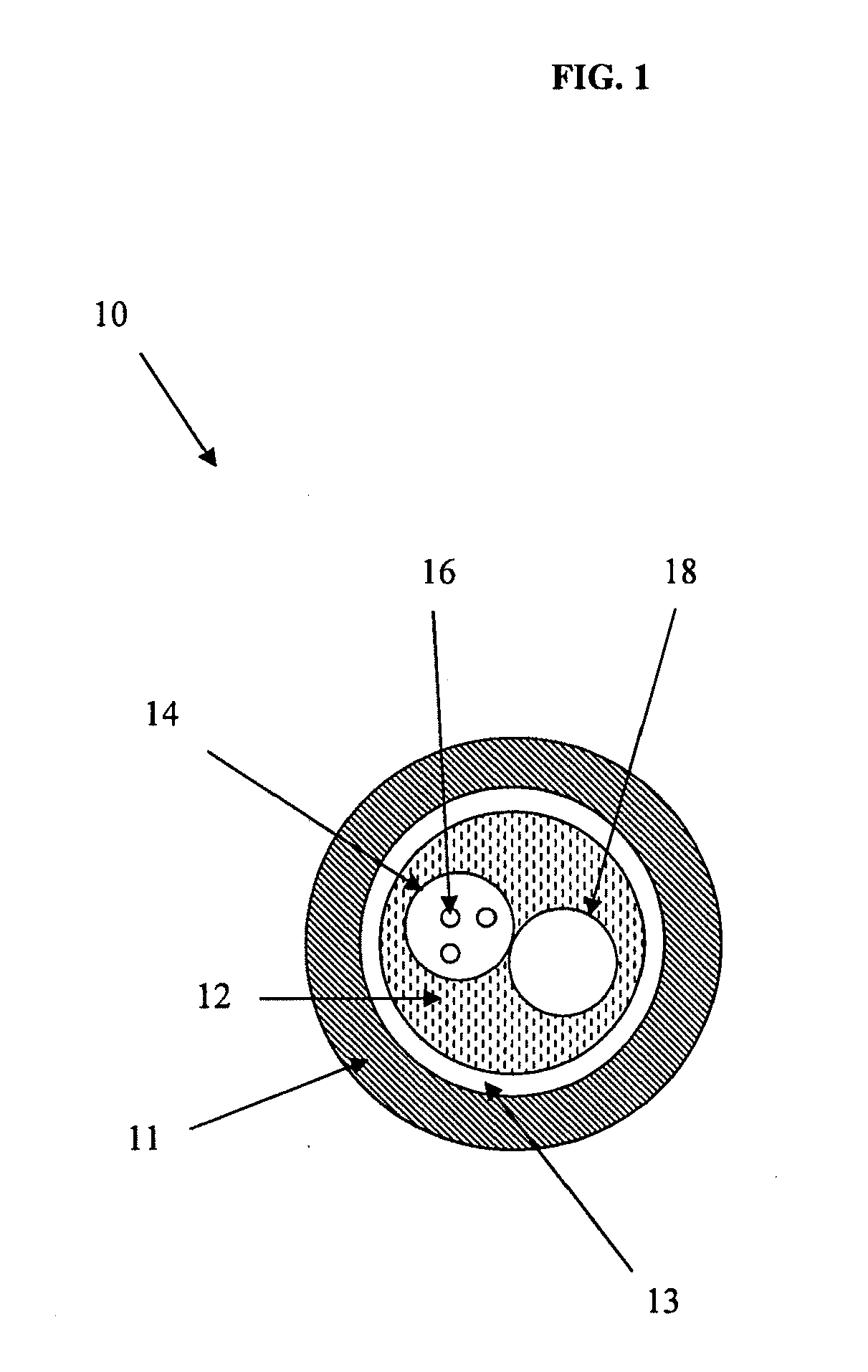
[0031]FIG. 1 illustrates a cross-sectional view of a fiber optic cable according to an exemplary embodiment of the present invention.

[0032]A fiber optic cable 10 is provided with an outer protective tube 11, a plastic extrusion 12, and an annulus 13 therebetween. Disposed within the plastic extrusion 12, there is provided a fiber optic tube 14 having a plurality of optical fibers 16 therein and an empty tube 18. At least one path, extending through the length of the fiber o...


PUM


Abstract

A breathable downhole fiber optic cable is provided having an outer protective tube; a fiber optic tube having a plurality of optical fibers contained therein; at least one annulus disposed between the outer protective tube and the fiber optic tube; and at least one path, extending through the length of the fiber optic cable, which provides a channel for a purge gas to flow for removing a second gas, such as hydrogen, from the fiber optic cable.

Description

CROSS-REFERENCE TO RELATED APPLICATIONS[0001]This application claims priority from U.S. Provisional Application No. 60 / 862,666, filed on Oct. 24, 2006, the disclosure of which is incorporated herein by reference in its entirety.BACKGROUND OF THE INVENTION[0002]1. Field of the Invention[0003]The present invention generally relates to fiber optic cables, and more particularly, relates to a breathable fiber optic cable which is ventilated to reduce hydrogen partial pressure next to the fiber.[0004]2. Description of the Related Art[0005]Fiber optic cables used for oil well applications where the cable is installed in the well have been problematic. One of the key concerns has been hydrogen darkening of the fiber. In the downhole environment, there is often free hydrogen present. Hydrogen can easily permeate the materials of the cable and diffuse into the optical fiber. The presence of hydrogen in the fiber will create an increase in transmission loss. This can make the systems that use ...

Claims


Application Information

Patent Timeline
Patent Type & Authority Applications(United States)
IPC IPC(8): G02B6/44
CPCG02B6/4415G01N33/005
Inventor HERBST, BRIAN
Owner AFL COMM LLC
Why Eureka
Try Eureka