Two-stage hydrocracking method

A hydrocracking and two-stage hydrogenation technology, which is applied in the fields of hydrotreating process, hydrocarbon oil treatment, petroleum industry, etc., can solve the unrelated problems such as how to increase the yield of heavy naphtha in the second stage

Active Publication Date: 2022-05-06
CHINA PETROLEUM & CHEM CORP +1
View PDF7 Cites 0 Cited by
  • Summary
  • Abstract
  • Description
  • Claims
  • Application Information

AI Technical Summary

Problems solved by technology

[0008] Among the above-mentioned existing technologies, there are those that optimize the energy consumption of the two-stage process, some that remove the pr

Method used


Image

  • Two-stage hydrocracking method
  • Two-stage hydrocracking method
  • Two-stage hydrocracking method

Examples


Embodiment 1

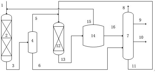
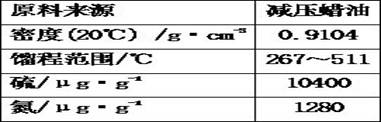
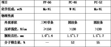
[0031] Process the raw materials in Table 1, use FF-66 hydrocracking pretreatment agent and FC-46 hydrocracking catalyst in the gradation of the first-stage reaction zone, the loading volume ratio of the two is 3:2, and the conversion rate of the first-stage control is 60% , the output liquid component enters the flash separator with an operating pressure of 13.5MPa and a temperature of 99°C. The liquid phase at the bottom of the separator enters the fractionation system, and the liquid phase at the bottom of the fractionation system and the gas phase at the top of the separator enter the second-stage reaction zone together. The second-stage filling uses FC-46 hydrocracking catalyst catalyst, and the single-pass conversion rate of the second stage is controlled. 60%, the liquid phase after the reaction enters the subsequent separation and fractionation system.

Embodiment 2

[0033] Process the raw materials in Table 1, use FF-66 and FC-46 hydrocracking catalysts in the reaction zone gradation of the first stage, the loading volume ratio of the two is 3:2, control the conversion rate of the first stage to 60%, and the liquid group of output The fraction enters the flash separator, whose operating pressure is 13.5MPa and temperature is 99°C. The liquid phase at the bottom of the separator enters the fractionation system, and the liquid phase at the bottom of the fractionation system and the gas phase at the top of the separator enter the second-stage reaction zone together. The second-stage filling uses FC-46 hydrocracking catalyst catalyst, and the single-pass conversion rate of the second stage is controlled. 70%, the liquid phase after the reaction enters the subsequent separation and fractionation system.

Embodiment 3

[0035] Process the raw materials in Table 1, use FF-66 and FC-46 hydrocracking catalysts in one-stage reaction zone gradation, the loading volume ratio of the two is 3:2, control the conversion rate of one-stage to 50%, and the liquid group of output The fraction enters the flash separator, whose operating pressure is 13.5MPa and temperature is 101°C. The liquid phase at the bottom of the separator enters the fractionation system, and the liquid phase at the bottom of the fractionation system and the gas phase at the top of the separator enter the second-stage reaction zone together. The second-stage filling uses FC-46 hydrocracking catalyst catalyst, and the single-pass conversion rate of the second stage is controlled. 60%, the liquid phase after the reaction enters the subsequent separation and fractionation system.


PUM


Abstract

The invention discloses a two-stage hydrocracking method, which comprises the following steps: a first-stage hydrocracking reaction effluent enters a flash separator to separate out a liquid phase flow and a gas phase flow, the liquid phase flow enters a fractionation system to separate out heavy naphtha and tail oil, the gas phase flow is mixed with the tail oil, and then a second-stage hydrocracking reaction is performed, and carrying out gas-liquid separation on the effluent of the second-stage hydrocracking reaction, taking the separated gas phase as recycle hydrogen of the first-stage hydrocracking reaction, and separating the liquid phase into a gas phase product, light naphtha, heavy naphtha and tail oil in a fractionation system. The method can increase the selectivity of the high-quality heavy naphtha product while reducing the deactivation rate of the two-stage hydrocracking catalyst.

Description

technical field [0001] The invention relates to a two-stage hydrocracking method, in particular to a two-stage hydrocracking method for producing heavy naphtha. Background technique [0002] Hydrocracking technology is the core of the combination of "oil and chemical fiber" and the key link of conversion, which has attracted more and more people's attention. Especially in today's high demand for chemical raw materials, its role is becoming more and more important. At present, the demand for fuel oil in the domestic market is sluggish. Compared with the increase in crude oil processing volume year by year, the proportion of fuel oil products in the refining product structure has been decreasing year by year. It is necessary to convert most of the crude oil into chemical raw materials with more vigorous market demand. It is inevitable that the product structure adjustment trend of oil refining enterprises will change from fuel type to chemical type. Hydrocracking units are re...

Claims


Application Information

Patent Timeline
IPC IPC(8): C10G67/02
CPCC10G67/02C10G2300/4006C10G2300/4012C10G2300/4018C10G2300/70
Inventor 王仲义崔哲彭冲吴子明庞宏
Owner CHINA PETROLEUM & CHEM CORP
Why Eureka
Try Eureka