Adaptive non-linearity compensation in coherent receiver

a non-linearity compensation and coherent receiver technology, applied in the field of optical communication, can solve problems such as degrading the overall system performance, and achieve the effects of reducing optical launch power, increasing signal-to-noise ratio, and increasing transmission distan

Inactive Publication Date: 2010-01-21
ALCATEL LUCENT SAS
View PDF24 Cites 60 Cited by
  • Summary
  • Abstract
  • Description
  • Claims
  • Application Information

AI Technical Summary

Benefits of technology

[0014]It is an object of the present invention to provide an efficient method and system for compensating SPM in an optical transmission system, particularly in an optical PDM-QPSK transmission system. By using the proposed SPM compensation method, it will be possible to increase the signal-to-noise ratio at the receiver and thereby it will be possible to allow for higher transmission distances at a given optical launch power or for lower optical launch powers at given transmission distances. It is a particular object of the present invention to provide an efficient and fast adaptation scheme for SPM compensation in a coherent receiver using a digital signal processor which allows for automatic adaptation of the filter parameters within the DSP to the actual non-linear distortion.

Problems solved by technology

This induces additional non-linear effects which degrade the overall system performance.

Method used


Image

  • Adaptive non-linearity compensation in coherent receiver
  • Adaptive non-linearity compensation in coherent receiver
  • Adaptive non-linearity compensation in coherent receiver

Examples


Embodiment Construction

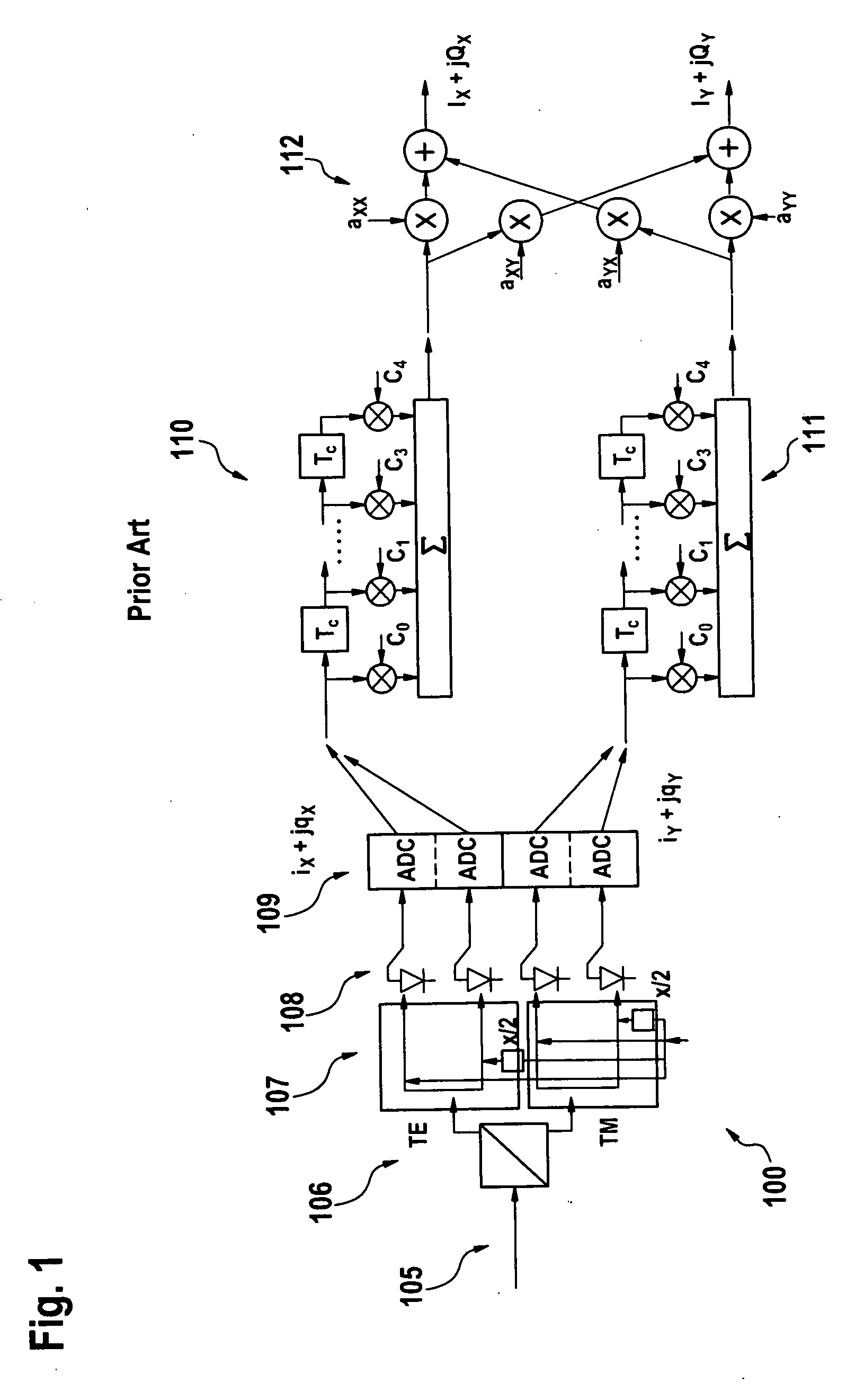
[0045]FIG. 1 was already discussed in the introductory part of this document.

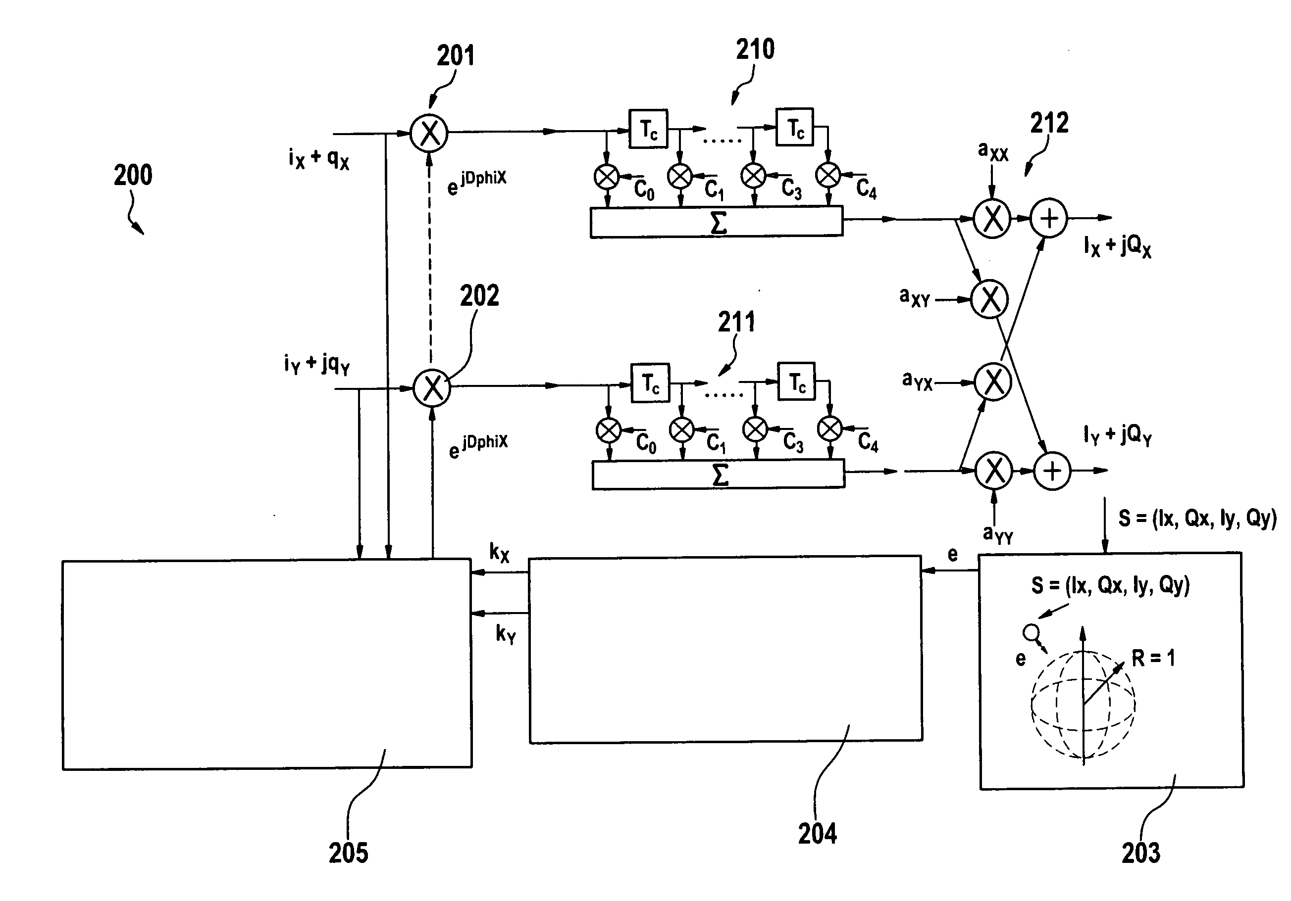
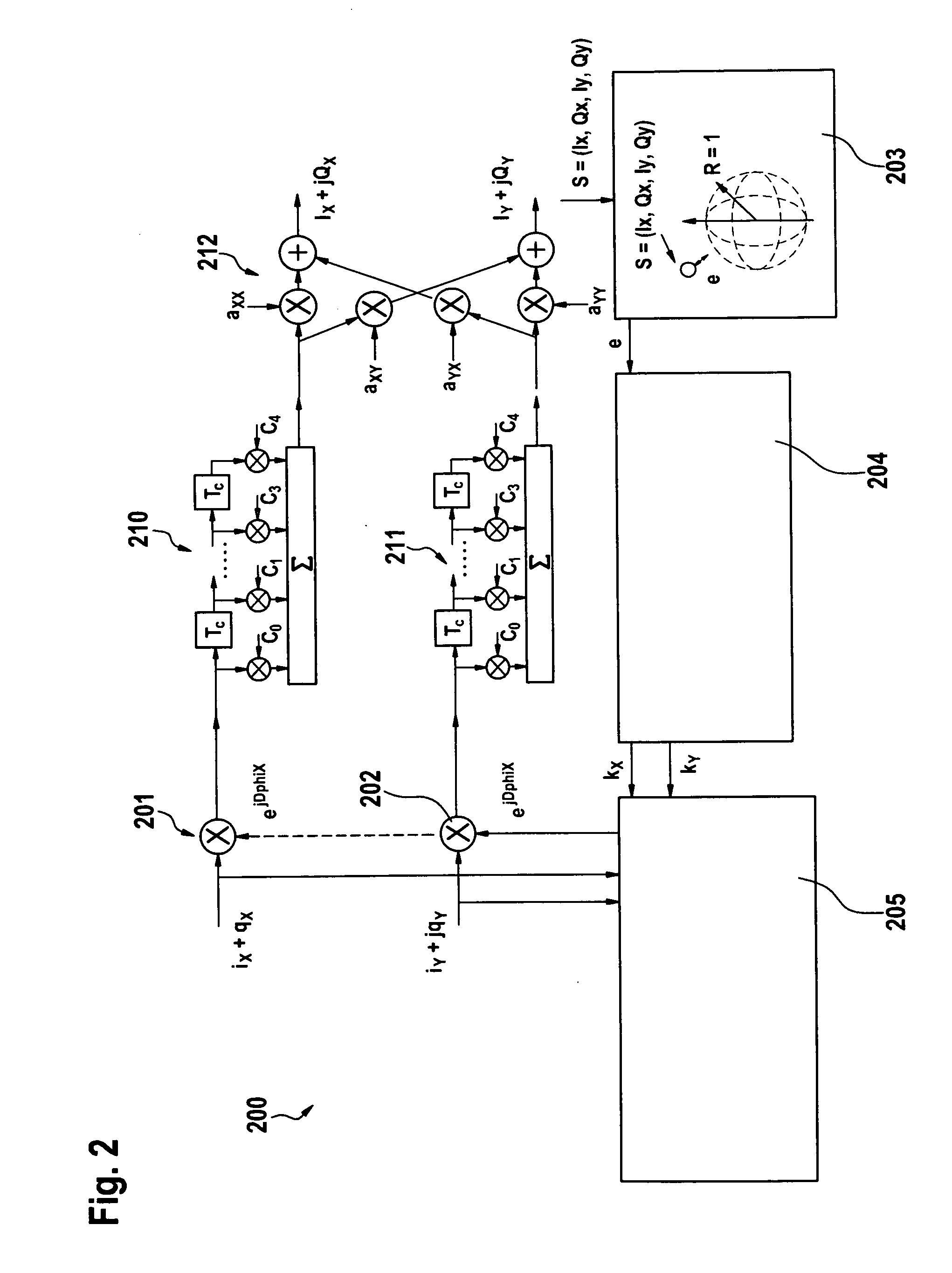
[0046]FIG. 2 illustrates an embodiment of the invention employing self-phase modulation compensation before CD equalization. In the shown example the optical receiver comprises two CD equalizers 210, 211 for each signal component and a polarization de-multiplexer 212. In addition, the optical receiver comprises a phase compensator or phase modulator 201, 202 for each transversal signal component ix+jqx and iy+jqy, respectively. The phase compensators employ an offset of the signal phase, i.e. they increase or decrease the signal phase, by the phase correctors or phase corrector values DphiX and DphiY for the “x” and the “y” signal components, respectively.

[0047]According to an aspect of the invention, the phase corrector values may be determined in a phase corrector determination unit 205, using the following equations:

DphiX=kx·(ix2+qx2+iy2+qy2),

DphiY=ky·(ix2+qx2+iy2+qy2),

wherein kx, ky are the proportional...


PUM


Abstract

The invention relates to optical communication, in particular to compensation of non-linear distortions incurred in high bit-rate optical communication systems. A method and system for compensating self-phase modulation at an optical receiver of an optical transmission system using polarization division multiplexing and a modulation scheme with constant amplitude is proposed. The method comprises the step of performing a phase modulation on a received signal, wherein the received signal comprises two signal components associated with two orthogonal polarizations, each component comprising an in-phase sub-component and a quadrature-phase sub-component, thereby spanning a four-dimensional space. The phase modulation is determined by evaluating an error signal which depends on the distance in the four-dimensional space between the received signal after the phase modulation and a four-dimensional sphere defined by target constellation points of the optical transmission system.

Description

FIELD OF THE INVENTION[0001]The invention is based on a priority application EP08290696.7 filed Jul. 16, 2008 which is hereby incorporated by reference.[0002]The invention relates to optical communication, in particular to compensation of non-linear distortions incurred in high bit-rate optical communication systems.BACKGROUND OF THE INVENTION[0003]State-of-the-art optical transmission schemes using polarization division multiplexing (PDM) of two independently phase modulated signals—e.g. two QPSK (quadrature phase-shift keying) signals—have a higher spectral efficiency compared to non-polarization diverse transmission schemes. In a coherent receiver, such PDM signals may be polarization de-multiplexed and distortion compensated by means of digital signal processing. Next generation transponders for terrestrial networks using bit-rates of 40 Gb / s and 100 Gb / s are expected to be based on polarization multiplexed QPSK (PDM-QPSK) modulation and coherent detection schemes. Using this te...

Claims


Application Information

Patent Timeline
Patent Type & Authority Applications(United States)
IPC IPC(8): H04B10/00H04B10/158H04B10/61H04B10/69H04J14/06
CPCH04B10/6161H04B10/6971H04B10/6165H04B10/2507H04B10/255H04B10/61
Inventor BULOW, HENNING
Owner ALCATEL LUCENT SAS
Why Eureka
Try Eureka