Portable security system and method

Inactive Publication Date: 2010-01-28
WAYNE DALTON CORP
View PDF10 Cites 71 Cited by
  • Summary
  • Abstract
  • Description
  • Claims
  • Application Information

AI Technical Summary

Benefits of technology

[0007]Accordingly, the portable security system of the present invention, according to one embodiment, includes a sensing unit where, when the sensing unit senses movement of itsel

Problems solved by technology

There are many known solutions to keeping doors and windows closed and locked but many of those solutions can cause entrapment in the event of a fire.
All of these prior art alarm systems known to the Applicant, however, are for electronic systems that are fixed or “hardwired” to the structure which only allows usage in a particular structure within whic

Method used


Image

  • Portable security system and method
  • Portable security system and method
  • Portable security system and method

Examples


Example

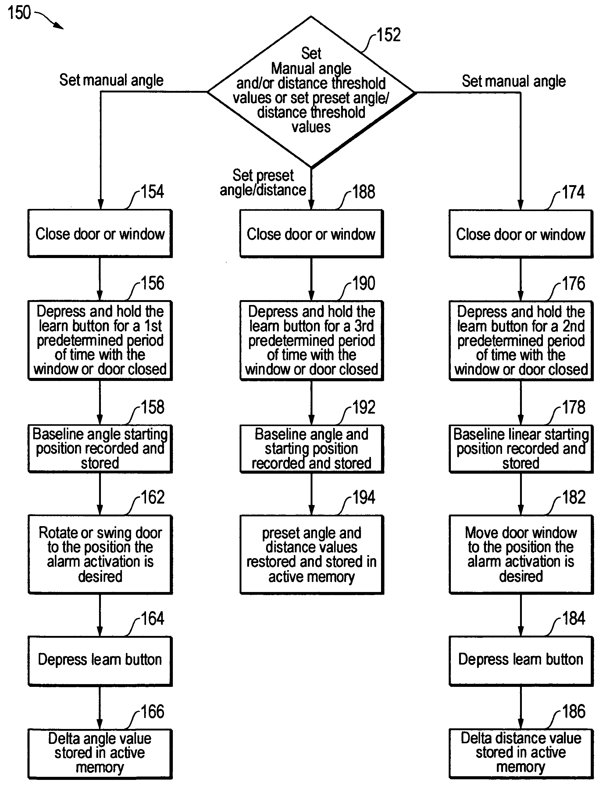
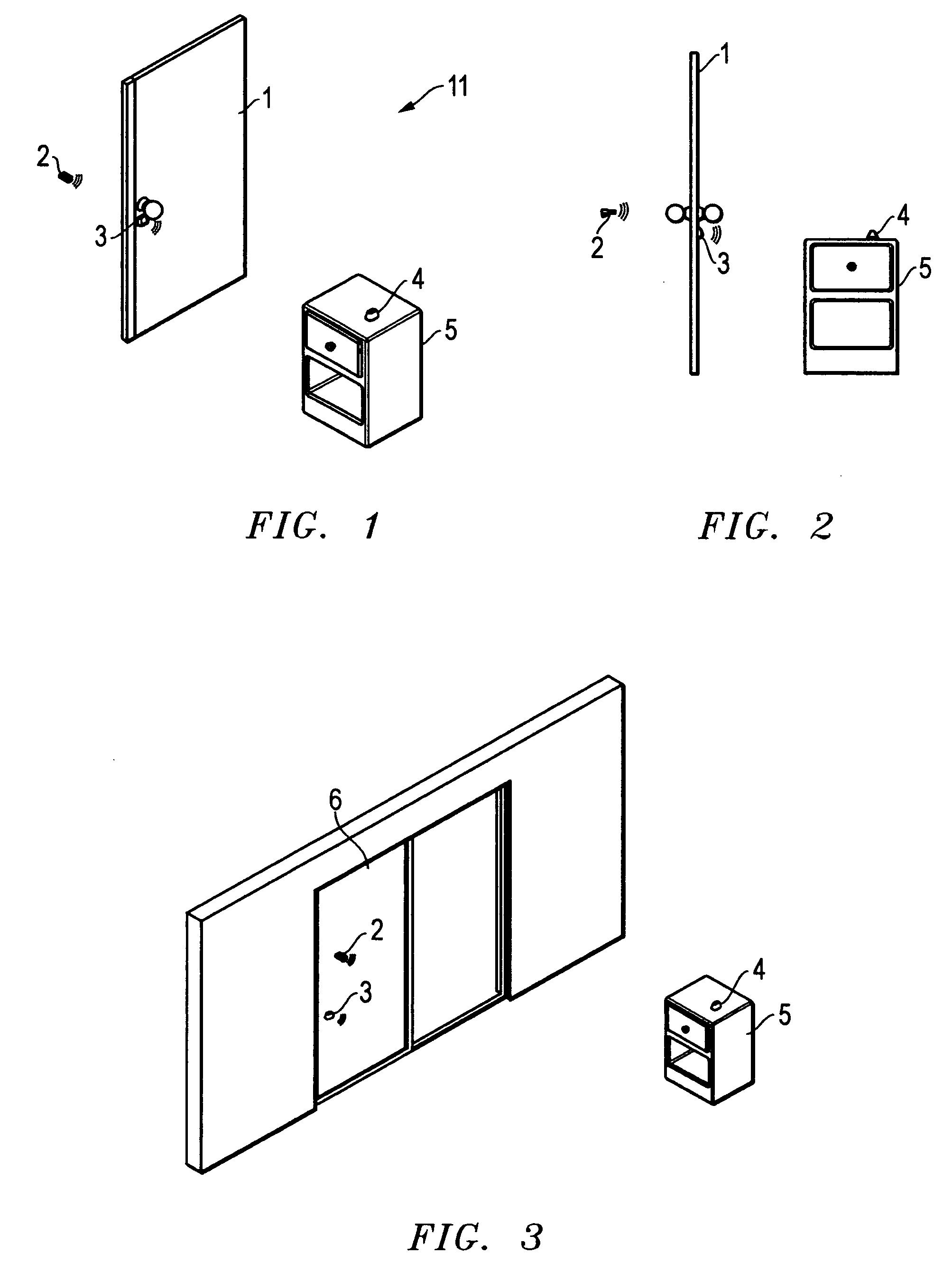
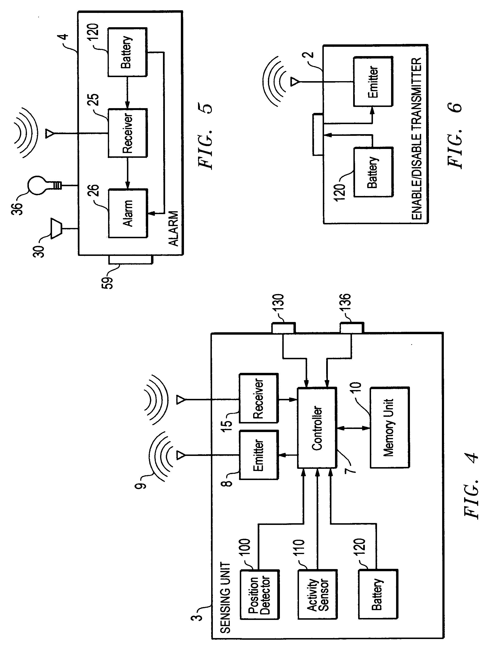
[0024]The preferred embodiment of the present invention is illustrated by way of example in FIGS. 1-8. Referring first to FIGS. 1-3, the portable security system 11, according to a preferred embodiment, includes an enable / disable transmitter 2 and a sensing unit 3. As will be discussed in detail hereafter, the sensing unit 3 is intended to be placed on a fenestration such as a door 1 or a window 6. According to the present invention, sensing unit 3 is conformed to send a signal to an alarm 4 when sensing unit 3 senses a change in its position due to a change in the position of the fenestration 1 or 6, for example only. This key feature of the present invention separates it from the prior art devices which themselves do not move and in fact are required to remain stationary in order to properly function.

[0025]Sensing unit 3 may be placed on and connected with objects, such as doors 1 or windows 6, by tapes, adhesives, hook and loop systems, tacks, screws, nails, or the like or any ot...


PUM


Abstract

A portable security system includes a sensing unit where the sensing unit is conformed to sense its own movement and to send a movement signal. An alarm is provided such that the alarm is activated to produce an alarm signal after receipt of the movement signal from the sensing unit.

Description

FIELD OF THE INVENTION[0001]This invention relates to a portable security system and method. In particular, in accordance with one embodiment, the invention relates, to a portable security system including a sensing unit where the sensing unit is conformed to sense its own movement and send a movement signal. An alarm is provided such that the alarm is activated to produce an alarm signal after receipt of the movement signal from the sensing unit.BACKGROUND OF THE INVENTION[0002]There has always been a need for devices and systems that would provide an alert signal of unwanted access into controlled areas, such as hotel or motel rooms and other living spaces in residential and commercial structures. Further, for example only and not by way of limitation, there are occasions that a parent would want to know if a child has managed to open a door and go outside of a structure. There are many known solutions to keeping doors and windows closed and locked but many of those solutions can ...

Claims


Application Information

Patent Timeline
IPC IPC(8): G08B13/08
CPCG08B13/08G08B13/26G08B13/2491
Inventor MULLET, WILLIS JAY
Owner WAYNE DALTON CORP
Why Eureka
Try Eureka