Fluid ejection apparatus

a technology of ejection apparatus and fluid, which is applied in the direction of printing, etc., can solve the problems of fluid leaching out, ejection nozzle blockage, fluid in the cap being blocked, etc., and achieve the effect of large negative pressure in the cap

Inactive Publication Date: 2010-01-28
SEIKO EPSON CORP
View PDF3 Cites 7 Cited by
  • Summary
  • Abstract
  • Description
  • Claims
  • Application Information

AI Technical Summary

Benefits of technology

[0010]An advantage of some aspects of the invention is that it provides a fluid ejection apparatus that avoids the abnormal ejection of fluid due to bubbles generated during an air sucking operation while also generating a large magnitude of negative pressure in the cap.

Problems solved by technology

Since the viscosity of fluid such as ink supplied to the ejection head increases over time, making it difficult to eject the fluid appropriately, a cap comes in contact with the ejection head to close the periphery of the ejection nozzle when the fluid is not ejected and thus suppresses an increase in the viscosity of the fluid.
Since the sucked fluid is attached to the periphery of the ejection nozzle after the cleaning operation, the ejection nozzle may be blocked if this state continues.
However, since the cap on which the cleaning operation has been performed is filled with the fluid drawn out from the ejection head, the fluid filled in the cap is leaked out when the cap is separated from the ejection head.
Since the viscosity of fluid in the ejection head increases, it is difficult to draw out the fluid.
However, if the magnitude of the negative pressure in the cap is increased by the suction pump, air flows in with a rush and generates bubbles in the cap when an air sucking operation is performed by the opening the air opening valve.

Method used


Image

  • Fluid ejection apparatus
  • Fluid ejection apparatus
  • Fluid ejection apparatus

Examples


Embodiment Construction

[0024]Hereinafter, an exemplary embodiment of the invention will be described in detail with reference to the accompanying drawings.

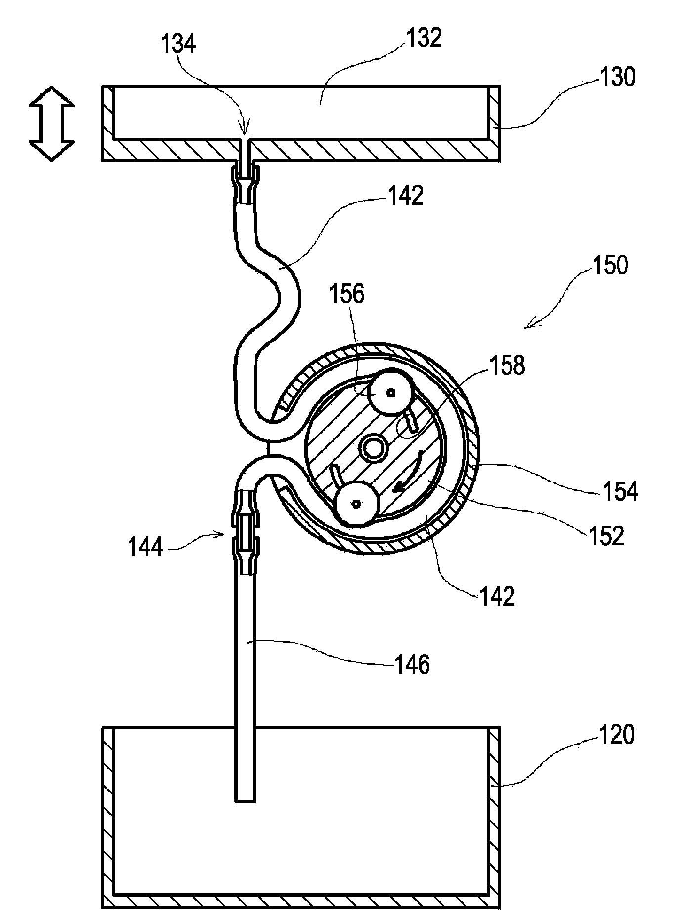
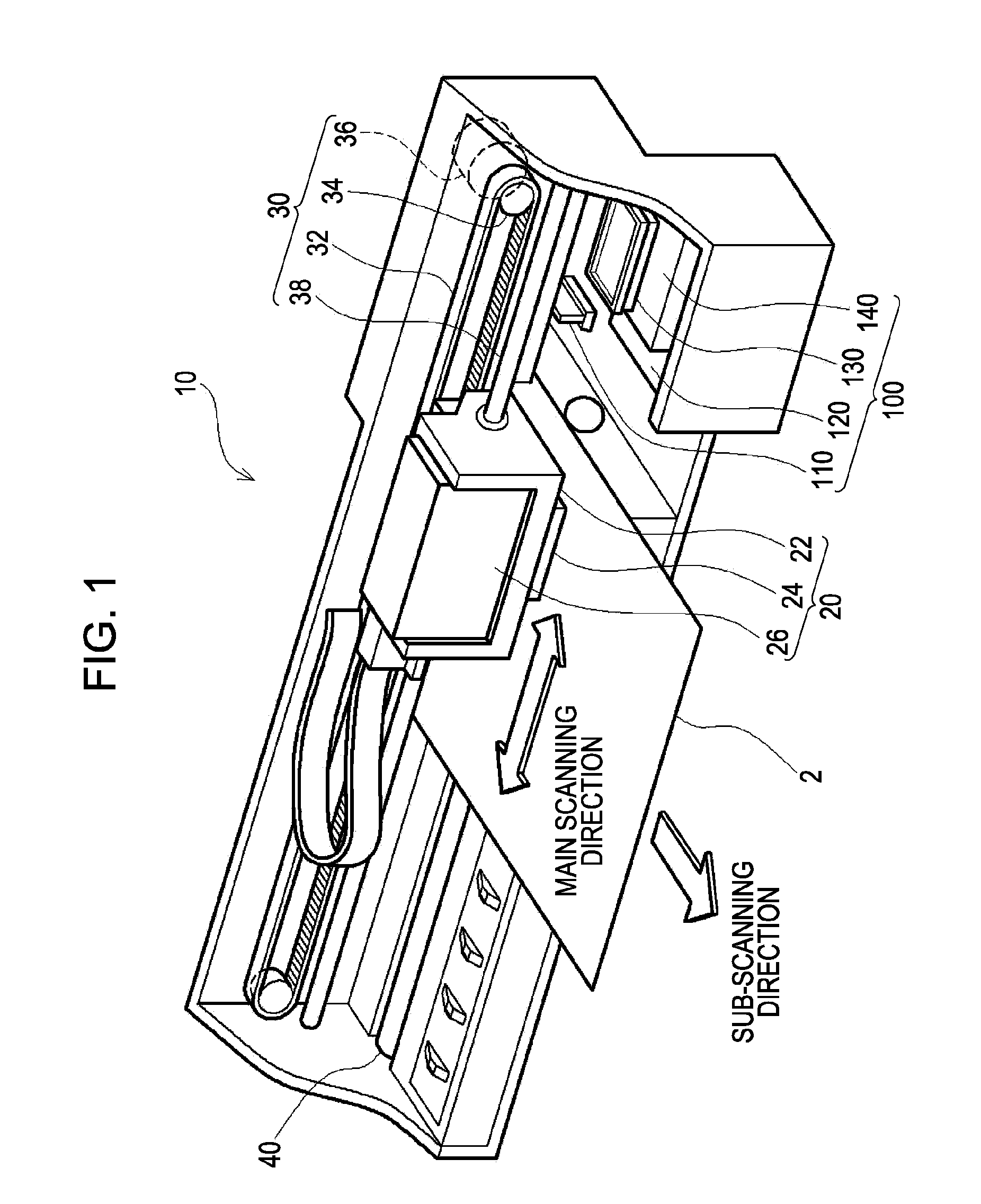
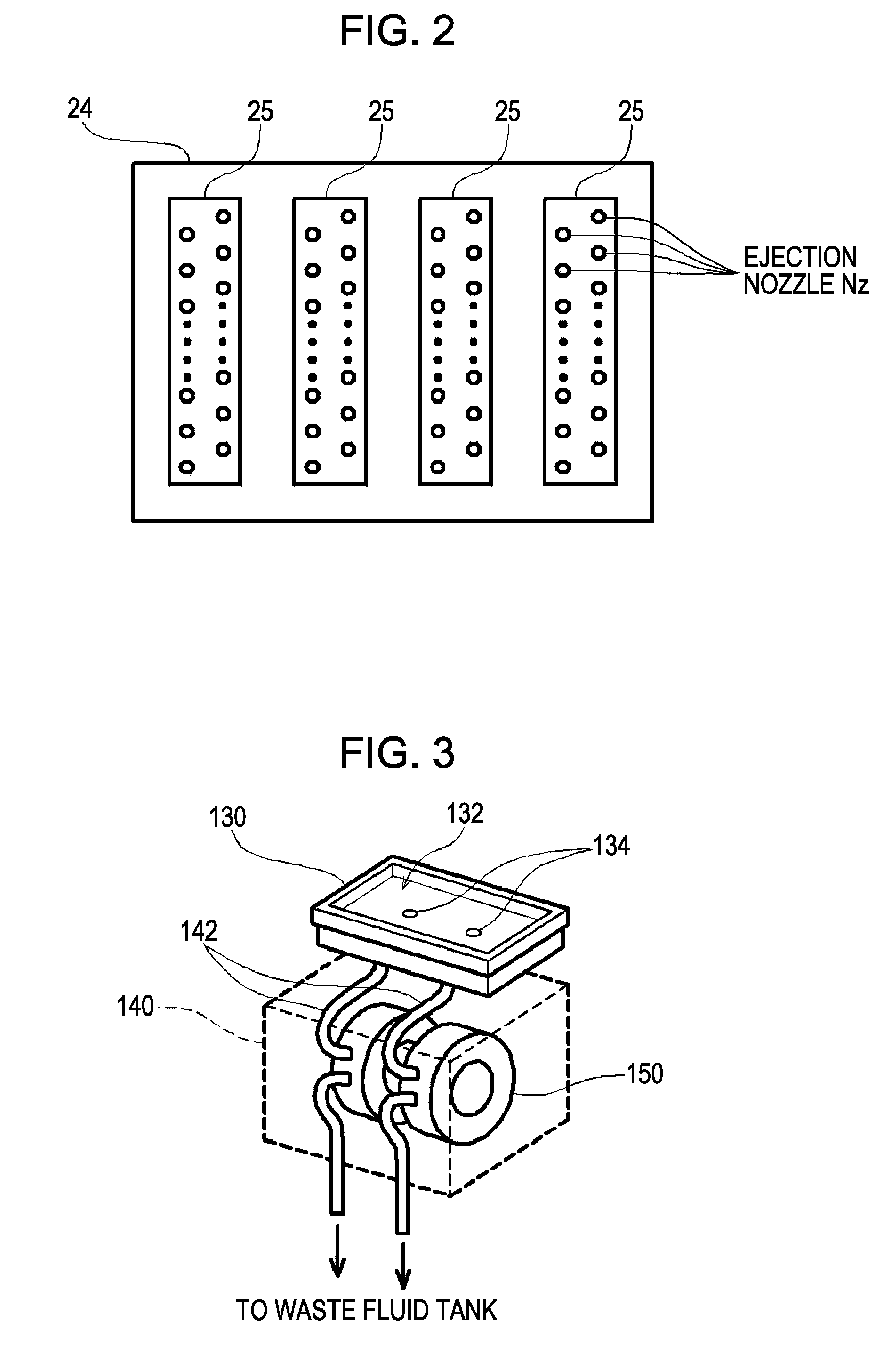
[0025]FIG. 1 is a perspective view schematically illustrating an example of a fluid ejection apparatus, i.e. an inkjet printer according to an embodiment of the invention. As illustrated in FIG. 1, the inkjet printer 10 includes a carriage 20 forming ink dots on a printing medium 2 while reciprocating in a main scanning direction, a drive mechanism 30 reciprocating the carriage 20, a platen roller 40 for feeding paper, i.e. the printing medium 2, and a maintenance mechanism 100 for maintaining a normal printing operation. The carriage 20 contains an ink cartridge 26 accommodating ink, a carriage case 22 to which the ink cartridge 26 is mounted, and a head assembly 24 mounted to the bottom (facing the printing medium 2) of the carriage case 22. As will be described below, the head assembly 24 includes a plurality of ejection heads for ejecting ink in ord...


PUM


Abstract

A fluid ejection apparatus that ejects fluid from an ejection nozzle in an ejection head includes a fluid receiver that has a concave portion for accommodating the ejected fluid and defines a closed space around the ejection nozzle when the concave portion contacts the ejection head. Suction pumps suck the fluid in the concave portion through suction ports in the concave portion. A fluid suction unit sucks the fluid in the ejection head through the ejection nozzle by operating the suction pumps such that the concave portion contacts the ejection head. An air suction unit sucks the air and the fluid in the concave portion of the fluid receiver after completion of suction of the fluid in the ejection head, by allowing at least one suction pump to reverse the air flow in collaboration with the operation of at least one other suction pump.

Description

BACKGROUND[0001]1. Technical Field[0002]The present invention relates to an apparatus that ejects a fluid from an ejection head.[0003]2. Related Art[0004]An inkjet printer can print an image of high quality by ejecting an accurate amount of ink to an appropriate position from a fine ejection nozzle. Using this technology, an electrode, a sensor, or a bio-chip may be manufactured by ejecting various fluids onto a substrate instead of ink.[0005]In this technology, a dedicated ejection head is used to eject an accurate amount of fluid such as ink to an appropriate position. Since the viscosity of fluid such as ink supplied to the ejection head increases over time, making it difficult to eject the fluid appropriately, a cap comes in contact with the ejection head to close the periphery of the ejection nozzle when the fluid is not ejected and thus suppresses an increase in the viscosity of the fluid. The state in which the cap is in contact with the ejection head in order to suppress an ...

Claims


Application Information

Patent Timeline
Patent Type & Authority Applications(United States)
IPC IPC(8): B41J2/165
CPCB41J2/16532B41J2/16523
Inventor MIYAZAWA, HISASHI
Owner SEIKO EPSON CORP
Why Eureka
Try Eureka