Endoscope insertion aid and endoscope apparatus

a technology of endoscope and insertion aid, which is applied in the field of endoscope insertion aid and endoscope apparatus, can solve the problems of difficult forward movement, longer endoscope time, and harder insertion of plunged insertion portion back

Inactive Publication Date: 2010-01-28
OLYMPUS MEDICAL SYST CORP
View PDF4 Cites 24 Cited by
  • Summary
  • Abstract
  • Description
  • Claims
  • Application Information

AI Technical Summary

Benefits of technology

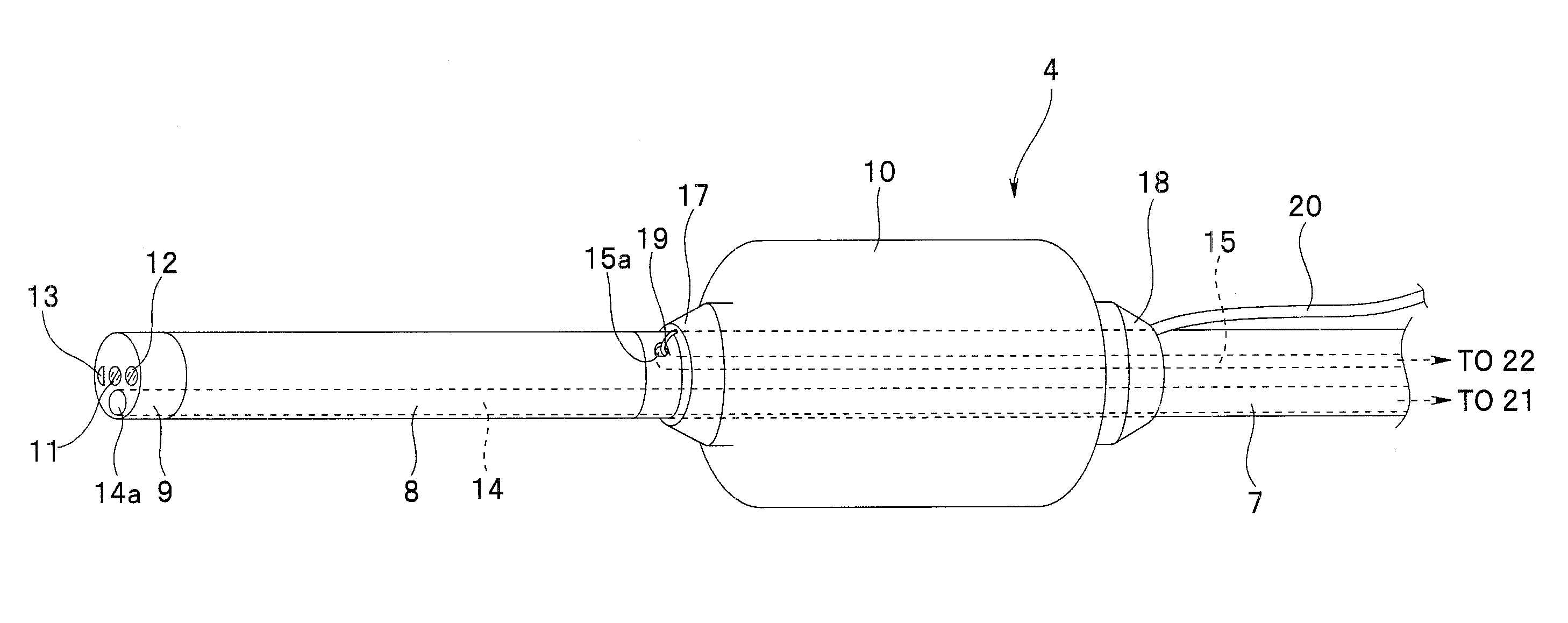
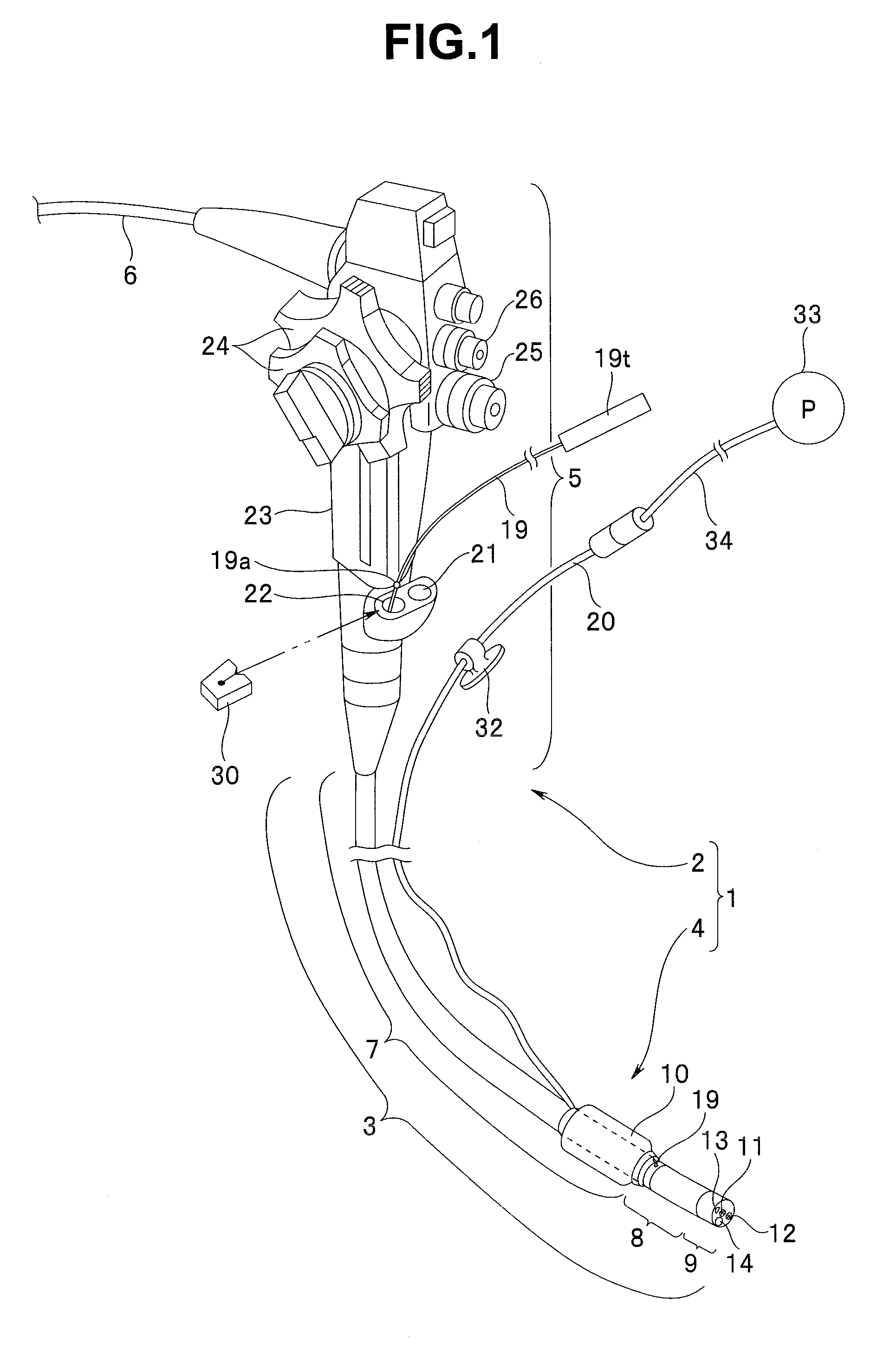
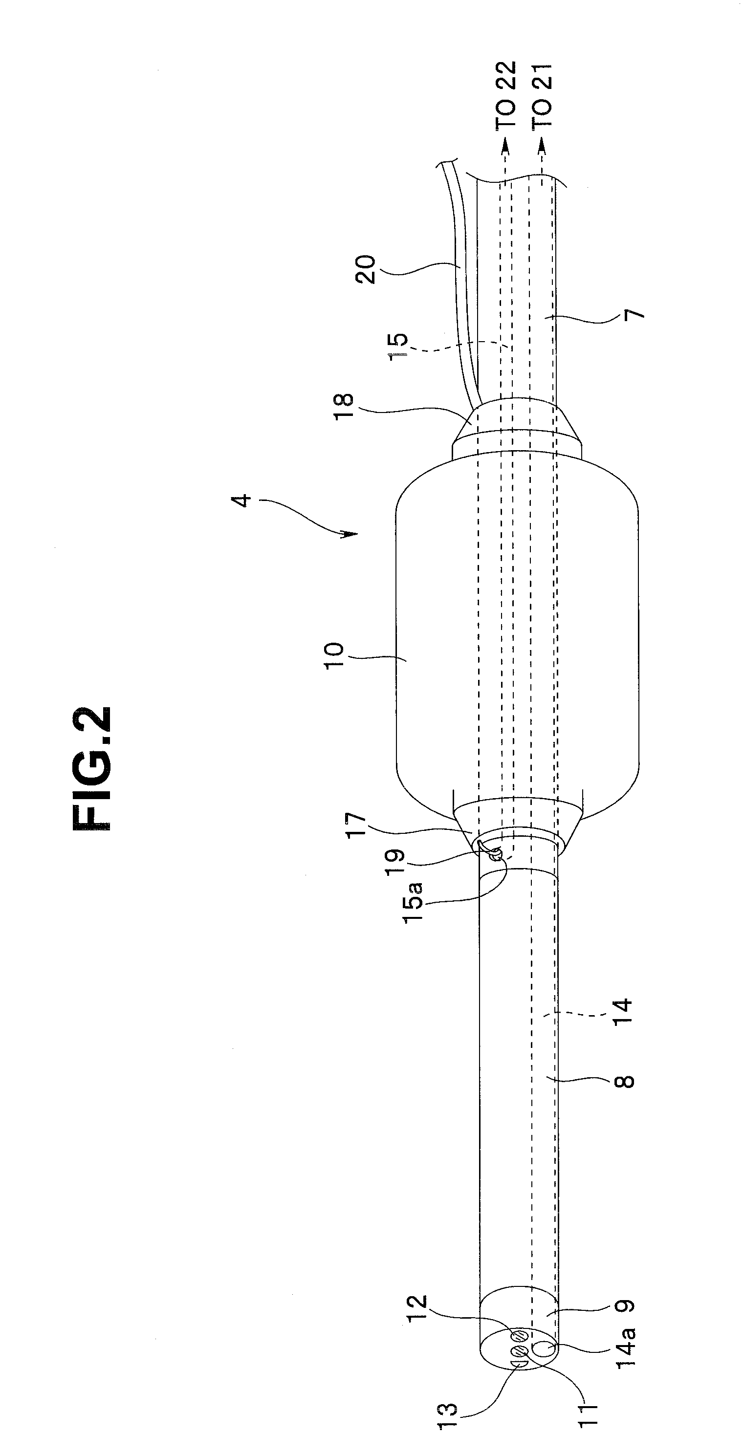
[0012]The present invention provides an endoscope insertion aid including: a tubular member which allows an insertion portion of an endoscope to be passed through and can move forward and backward relatively along an insertion axis of the passed insertion portion; a holding unit which, being provided on an outer peripheral side of the tubular member, can be inflated and deflated with supply and discharge of a fluid; a thread-like member which, being connected at one end to the tubular member and passed at the other end into a channel in the insertion portion through an opening portion communicated with the channel, extends from an opening of the channel, the opening being arranged on a proximal end side of the endoscope; a thread-like member fixing unit which restr

Problems solved by technology

However, the intestinal tract into which the insertion portion of the endoscope is pushed is a soft, internally narrow, long, and intricately winding organ which is not secured to the body.
In that case, when the surgeon relaxes pushing force, the plunged insertion portion may be returned to its original

Method used


Image

  • Endoscope insertion aid and endoscope apparatus
  • Endoscope insertion aid and endoscope apparatus
  • Endoscope insertion aid and endoscope apparatus

Examples


second embodiment

[0150]FIGS. 19 to 31 concern a second embodiment, where FIG. 19 is an explanatory diagram showing how an improved thread-like member is led out of a second channel entrance port; FIG. 20 is a perspective view illustrating a configuration of an improved rotary-dial thread fixing unit; FIG. 21 is a perspective view showing how the rotary-dial thread fixing unit shown in FIG. 20 is mounted near the second channel entrance port of the endoscope; FIG. 22 is a sectional view of a mounting portion of the endoscope and rotary-dial thread fixing unit shown in FIG. 21; FIG. 23 is an exploded block diagram showing a concrete configuration of the rotary-dial thread fixing unit shown in FIG. 20; FIG. 24 is a block diagram of the rotary-dial thread fixing unit shown in FIG. 23 as viewed from a mounting direction of the endoscope; FIG. 25 is a block diagram of the rotary-dial thread fixing unit shown in FIG. 23 as viewed from above; FIG. 26 is a block diagram of the rotary-dial thread fixing unit ...

third embodiment

[0193]FIGS. 34 to 37 concern a third embodiment, where FIG. 34 is a partial cutaway, sectional view illustrating a configuration of an endoscope insertion aid equipped with inner balloons instead of the thread-like member; FIG. 35 is a block diagram as viewed along arrow XXXV in FIG. 34; FIG. 36 is a sectional view taken along line XXXVI-XXXVI in FIG. 34; and FIG. 37 is an exploded perspective view of the endoscope insertion aid in FIG. 34.

[0194]In FIGS. 34 to 37, the same components as those in the first and / or second embodiments are denoted by the same reference numerals as the corresponding components in the first and / or second embodiments, and description thereof will be omitted. Only differences will be described.

[0195]An endoscope apparatus 1 according to the present embodiment is equipped with the endoscope insertion aid 4B shown in FIG. 34. The endoscope insertion aid 4B, which has substantially the same configuration as the endoscope insertion aid 4, includes an inner ballo...


PUM


Abstract

An endoscope insertion aid includes: a tubular member which allows an insertion portion of an endoscope to be passed through in a manner being capable of moving forward and backward. A holding unit, which is provided on an outer peripheral side of the tubular member, can be inflated and deflated. A thread-like member, which is connected at one end to the tubular member and passed at the other end into a channel, extends from an opening of the channel. A thread-like member fixing unit which restrains the thread-like member and thereby restricts movement of the tubular member. A restraining member which supplies and discharges the fluid into/from the holding unit, being disposed to the insertion portion, being connected at one end to the tubular member, extends at the other end to the proximal end side of the insertion portion. A restraining member fixing unit which holds the tubular member.

Description

[0001]This application is claims benefit of Japanese Application No. 2008-193837 filed in Japan on Jul. 28, 2008, the contents of which are incorporated by this reference.BACKGROUND OF THE INVENTION[0002]1. Field of the Invention[0003]The present invention relates to an endoscope insertion aid and endoscope apparatus suitable for smoothly inserting an insertion portion of an endoscope into an intestinal tract such as the large intestine or small intestine.[0004]2. Description of the Related Art[0005]Generally, an endoscope includes an operation portion intended to be gripped by a surgeon and equipped with various operation switches and the like, and an insertion portion inserted into a body cavity. Starting from a distal end, the insertion portion includes a distal end portion, bending portion, and flexible tubular portion, all of which are provided continuously. The flexible tubular portion has flexibility and elongated shape, extending from the operation portion. The bending porti...

Claims


Application Information

Patent Timeline
IPC IPC(8): A61B1/01
CPCA61B1/00082A61B1/31A61B1/015A61B1/01
Inventor MAKIYAMA, SATOSHI
Owner OLYMPUS MEDICAL SYST CORP
Why Eureka
Try Eureka