

Image compressing method, image compressing apparatus and image forming apparatus
a compression method and compression technology, applied in the field of image compression method, image compression apparatus and image forming apparatus, can solve the problems of lossy compression of original color image obtained before color decreasing processing, complicated control process,
- Summary
- Abstract
- Description
- Claims
- Application Information
AI Technical Summary
Benefits of technology
Problems solved by technology
Method used
Image

Examples
embodiment 1
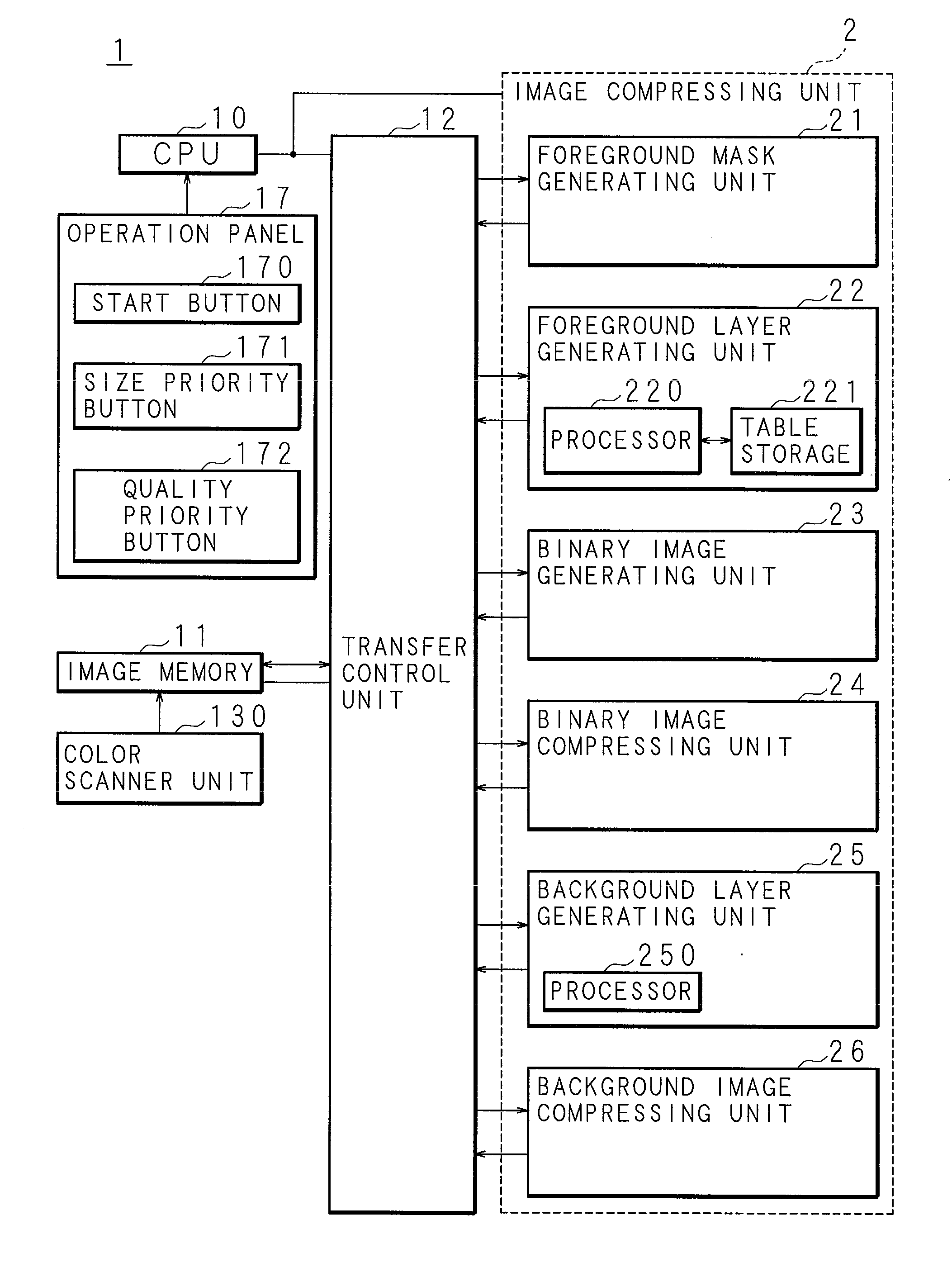
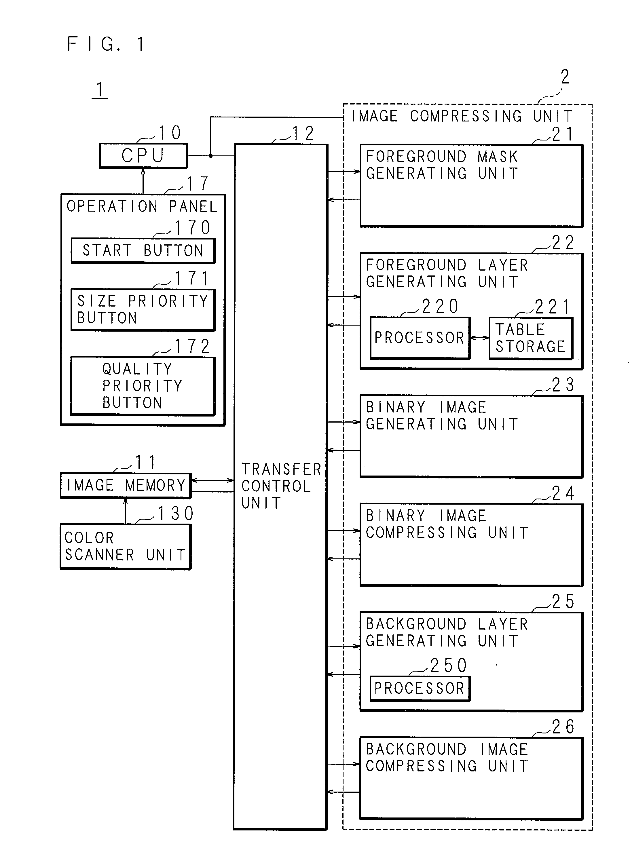
[0084]FIG. 1 is a block diagram illustrating the configuration of a principal part of an image compressing apparatus according to Embodiment 1. In FIG. 1, a reference numeral 1 denotes an image compressing apparatus, and the image compressing apparatus 1 performs a color image compression process for compressing a color image inputted to the image compressing apparatus 1. A color image is generally separated into a foreground layer and a background layer, the foreground layer is further separated into binary images, the respective binary images are subjected to lossless compression, the background layer is subjected to lossy compression, and the thus obtained lossless compressed images and lossy compressed image and information to be used for decompressing these images are brought into one file (hereinafter referred to as a compression file). As the information to be used for decompressing a lossless compressed image, an index color table (hereinafter referred to as an IC table) is ...
embodiment 2
[0181]FIG. 20 is a block diagram illustrating the configuration of a principal part of an image forming apparatus according to Embodiment 2 of the invention. In this embodiment, a digital multi-function printer having a color copier function and a color scanner function is described as an example of the image forming apparatus.
[0182]The image forming apparatus includes a color image input apparatus 13, a color image processing apparatus 14, a color image output apparatus 15, a communication device 16 and an operation panel 17. The color image processing apparatus 14 includes an A / D converter 140, a shading correction section 141, an input tone correction section 142 and a compressing section 143, and the compressing section 143 corresponds to the image compressing apparatus 1 of Embodiment 1. The operations of the respective components of the image forming apparatus are controlled by a CPU not shown corresponding to the CPU 10 of Embodiment 1.
[0183]The color image processing apparat...
embodiment 3
[0196]According to the present invention, the image compressing method of the invention may be recorded in a computer-readable recording medium in which program codes (an execute form program, an intermediate code program and a source program) of a computer program to be executed by a computer are recorded. As a result, a recording medium storing the program codes for causing a computer to execute the present image compressing method is portably provided.
[0197]It is noted that the recording medium may be a program medium using a memory not shown such as a ROM for performing the process by a microcomputer or may be a program medium obtained by providing a program code reader as an external memory not shown and loading the recording medium in the reader for reading the program codes.
[0198]In both cases, the stored computer program may be executed through access by a microprocessor or may be executed by a method in which the program codes are read to be downloaded to a program storage ...
PUM
 Abstract
Description
Claims
Application Information