Method and system for implementing subarea overlapping using mirror-image radio frequency unit

A radio frequency unit, mirroring technology, applied in electrical components, communication between multiple stations, network planning, etc., can solve problems such as signal distortion, shortened antenna coverage distance, and large number of channels to avoid noise and attenuation, avoid Noise, Demand Reduction Effect

Inactive Publication Date: 2008-03-12
ZTE CORP
View PDF2 Cites 15 Cited by
  • Summary
  • Abstract
  • Description
  • Claims
  • Application Information

AI Technical Summary

Problems solved by technology

[0005] In the OTSR system, each antenna needs to correspond to an independent uplink channel processing unit in the baseband and intermediate frequency parts, so the number of channels occupied is large; and the power in the downlink direction is evenly distributed to multiple antennas, which may cause signal distortion and cause antenna coverage. shortening of distance
In a conventional multi-channel system, each antenna corresponds to an independent uplink and downlink channel processing unit; however, if a coupler is used to combine the analog signals of multiple antennas into one channel processing unit, it is not conducive to the management of multiple antennas. At the same time, because the analog signal may be distorted during the transmission process, the signal coverage distance of the uplink and downlink RRUs will be shortened, and the smart antenna technology cannot be used.
[0006] It can be seen that the realization of partition coverage in wireless communication systems faces many challenges

Method used


Image

  • Method and system for implementing subarea overlapping using mirror-image radio frequency unit
  • Method and system for implementing subarea overlapping using mirror-image radio frequency unit
  • Method and system for implementing subarea overlapping using mirror-image radio frequency unit

Examples


Embodiment 1

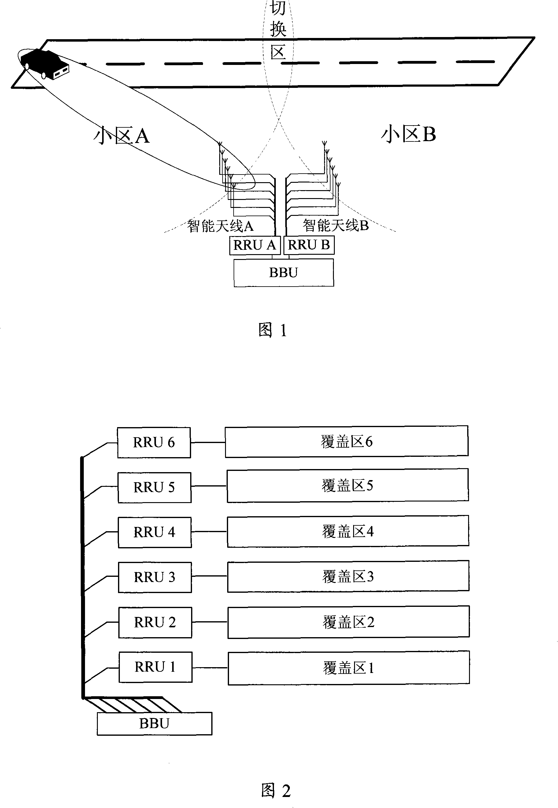
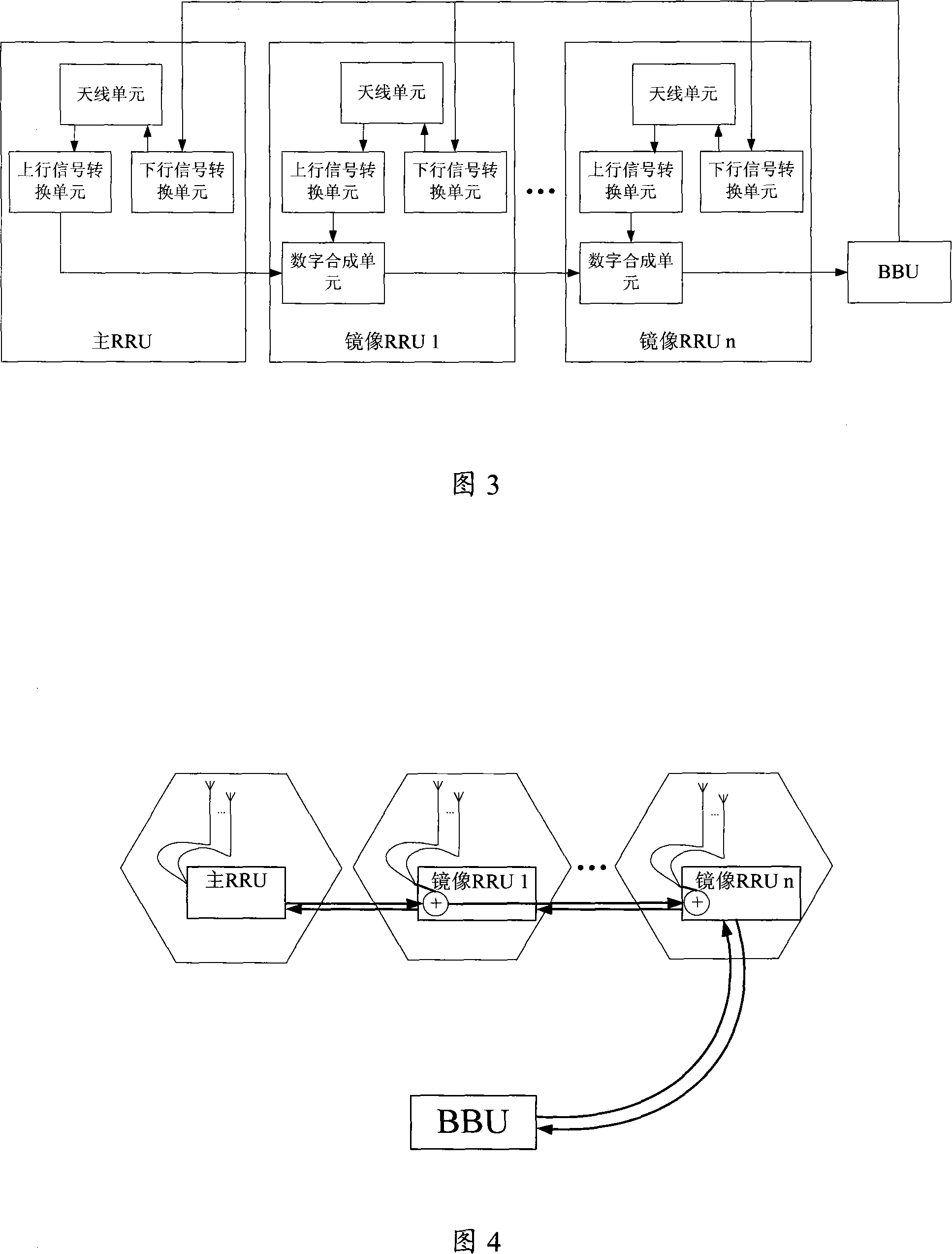
[0043] Embodiment 1 is a scenario where the technical solution of the present invention is applied to one cell covering multiple areas to reduce network construction costs, as shown in FIG. 4 . Antennas in N independent areas are respectively connected to respective RRUs.

[0044] In the downlink direction, the BBU transmits the baseband digital domain signal that needs to be sent to the RRU. Therefore, the signals sent by N RRUs are exactly the same; in the uplink direction, the RRU independently processes the received signal of the antenna and outputs the baseband digital domain signal. The signal transmitted by the RRU and the local sampling signal are digitally superimposed according to the identification of the signal channel, and finally the BBU performs baseband processing on the superimposed signal.

[0045] At the same time, the RRU independently performs power calibration in its coverage area, so that one cell can cover N different coverage areas, thereby achieving t...

Embodiment 2

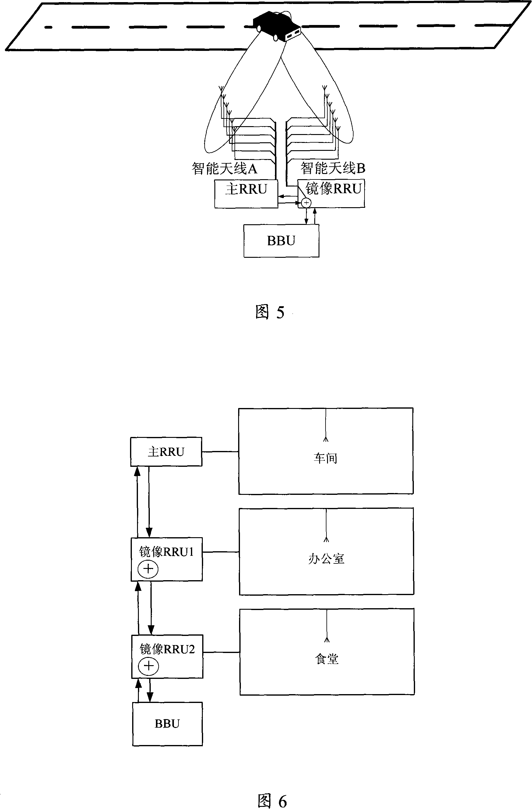
[0046] Embodiment 2 is a scene where the technical solution of the present invention is applied to expressway coverage, as shown in FIG. 5 . Taking TS-SCDMA technology as an example, it is assumed that each group includes two sets of linear array smart antennas with M antennas, facing two directions of the highway respectively, and each group of smart antennas is connected to one RRU.

[0047] The same function as the existing RRU is that the RRUs perform power calibration and antenna correction on their respective smart antennas. The difference from the existing RRU function is: in the downlink direction, the digital baseband signal output by the BBU is transmitted to the cascaded RRU at the same time, and the two RRUs obtain the same baseband signal and perform subsequent downlink signal processing; in the uplink direction, each RRU pair The signals received by the M antennas are independently processed in the corresponding M signal channels, and the baseband data of the M a...

Embodiment 3

[0049] Embodiment 3 is a scenario where the technical solution of the present invention is applied to indoor coverage, as shown in FIG. 6 . Taking WCDMA technology as an example, it is assumed that each antenna covers a different area, and each antenna is connected to one RRU.

[0050] In the downlink direction, the digital baseband signal output by the BBU is transmitted to all cascaded RRUs. Each RRU obtains the same baseband signal and performs subsequent downlink signal processing; in the uplink direction, each RRU processes the signal received on the antenna independently. And sample the baseband data of the antenna port, then saturate and superimpose the data transmitted by the previous RRU with the sampled data of the local antenna, and pass it to the next RRU, and the last RRU transmits the superimposed data to the BBU for baseband processing.

[0051] It can be seen that by using mirrored RRU technology in multiple unrelated areas, multiple coverage zones of the same ...


PUM


Abstract

The invention discloses a method and a system which can realize zoning coverage through mirror image RRU. The system comprises a plurality of cascaded RRUs and BBUs connected onto the RRUs, and the cascaded RRU comprises a main RRU and a mirror image RRU. In the cascaded RRUs, each RRU transforms analog signal received by at least an antenna from the corresponding covering region into digital signal, therein, the mirror image RRU overlaps the digital signal transmitted from the RRU of the previous cascade and the digital signal gathered in the locality and transfers to the next cascade, the transfer is performed stage by stage until one mirror image RRU transfers the overlapped digital signal into the signal channel of the BBU to perform the baseband processing. The adoption of the invention maintains the coverage radius of each RRU, the coverage capacity in the cell can be expanded under the unlimited capacity, and simultaneously the demand to the BBU processing capacity is reduced.

Description

technical field [0001] The invention relates to a partition coverage technology based on a baseband unit (BBU) and a radio frequency unit (RRU) structure in a mobile communication system, in particular to a method and a system for realizing partition coverage by using a mirrored RRU. Background technique [0002] Partitioned coverage of a wireless communication system is an essential requirement for providing continuous service. However, due to the characteristics of wireless signal propagation in the coverage area and the limited power amplifier of the wireless system, multi-channel technology has become an important means to solve partition coverage. [0003] In the international patent application named "Cellular Telecommunications Network with an OMNI Directional TransmitterType and a Sectored Receiver Type" (OTSR) filed on December 20, 2000 with the patent number WO / 2001 / 047148, an omnidirectional transmission fan is disclosed. The method of regionalized reception to i...

Claims


Application Information

Patent Timeline
Patent Type & Authority Applications(China)
IPC IPC(8): H04Q7/36H04B7/26H04W16/18H04W16/32
CPCH04W16/28
Inventor 丁美玲陈林江顾巨峰
Owner ZTE CORP
Why Eureka
Try Eureka