
Tool belt mountable device for retractable tool lanyards

a tool belt and tool belt technology, applied in the field of retractable tool belts, can solve the problems of hazard to personnel and/or equipment located under the work area, affecting the use of the hand, and affecting the safety of users,

Inactive Publication Date: 2010-02-11
PURE SAFETY GRP INC
View PDF23 Cites 17 Cited by
  • Summary
  • Abstract
  • Description
  • Claims
  • Application Information

AI Technical Summary

Benefits of technology

"The present invention provides a belt mountable tool lanyard device that can house multiple retractable tool lanyards. The device includes an enclosure with multiple parallel chambers for receiving the lanyard components, and a belt loop for mounting on a tool belt. The device also includes a clip receiving member and a releasable tool connector for attaching the device to a tool belt. The device can be slidably positioned to a preferred location on the tool belt. The technical effects of the invention include the ability to conveniently and securely attach a tool lanyard device to a tool belt, allowing for easy access to tools while working."

Problems solved by technology

The use of hand tools (i.e. hammers, screw drivers, pliers, ratchets, levels, flashlights, tape measures, etc.) when working in overhead situations have the potential to be articles that can cause damage or injury.
In these working conditions the hand tools if dropped could cause a hazard to personnel and / or equipment located beneath where the work is being performed.
While in use, if the tool is mishandled, bumped, or jarred, it can become dislodged from the user's hand and free to fall to whatever is beneath the worker.
Another hazardous circumstance can arise when working above vital plant equipment.
If a tool is dropped into an area where there is vital equipment, the dropped tool could cause severe damage to the equipment below.
Even with the more elaborate tooling lanyards available on the market, there is still a high percentage of dropped tools occurring due to the inconvenience and cumbersome methods of detaching and reattaching different tools to the wrist lanyard in addition to the normal use of the tool.

Method used


Image

  • Tool belt mountable device for retractable tool lanyards
  • Tool belt mountable device for retractable tool lanyards
  • Tool belt mountable device for retractable tool lanyards

Examples


Embodiment Construction

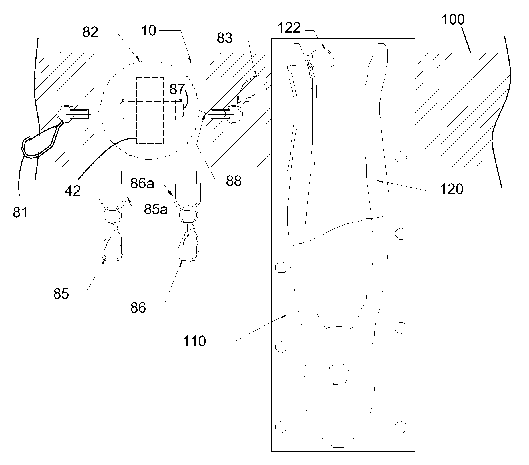
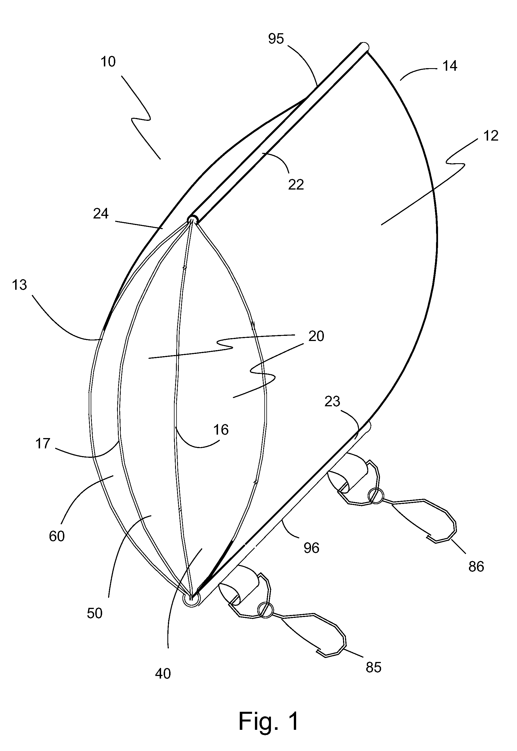
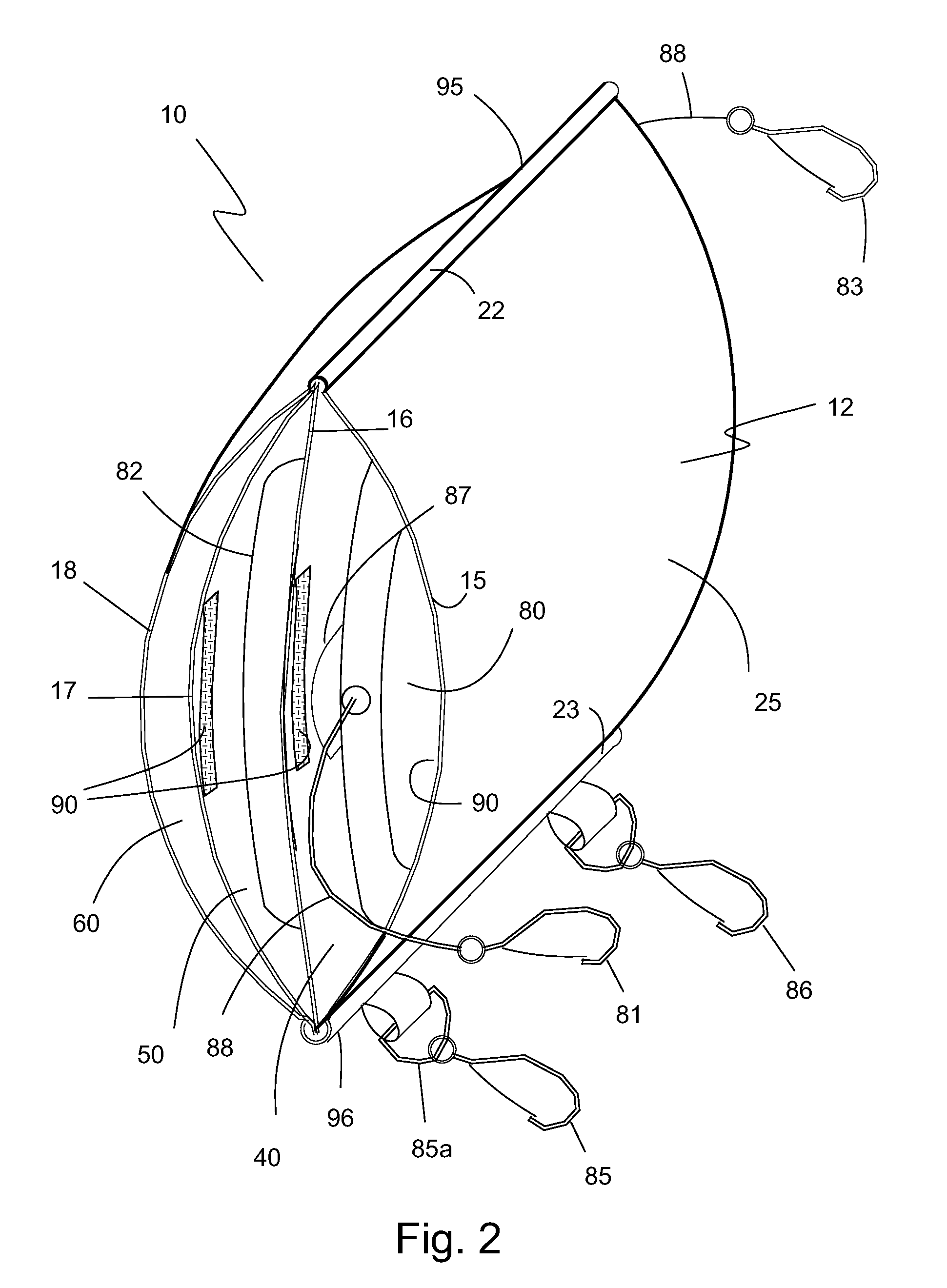
[0026]The preferred embodiment of the present invention is illustrated in FIGS. 1-3. FIG. 1 illustrates one embodiment of a belt mountable tool lanyard device 10 of the present invention. Tool lanyard device 10 has an enclosure 12 with diametrically opposed first and second openings 13, 14, and a plurality of internal dividers 16, 17 forming a plurality of lanyard device chambers or open-ended pockets 19, namely, a first open-ended lanyard pocket 40, a second open-ended lanyard pocket 50 and a belt loop pocket 60. Second open-ended lanyard pocket 50 is layered to first open-ended lanyard pocket 40 and belt loop pocket 60 is layered to second open-ended lanyard pocket 30. Each chamber or pocket 19 has at least one chamber opening 20 that faces in the same direction as one of the first and second openings 13, 14. At least one of the chambers 19 has a second chamber opening 22 (not shown) diametrically opposed to the one chamber opening 20 forming a belt receiving loop 24.

[0027]Tool la...


PUM


Abstract

A belt mountable tool lanyard device includes an enclosure having diametrically opposed first and second openings, a plurality of internal dividers within the enclosure forming a plurality of lanyard device chambers wherein each chamber has at least one chamber opening that faces in the same direction as one of the first and second openings and wherein at least one of the plurality of chambers has a second chamber opening diametrically opposed to the one chamber opening forming a belt receiving loop.

Description

[0001]This application claims the benefit of U.S. Provisional Patent Application No. 61 / 087,205, filed Aug. 8, 2008.BACKGROUND OF THE INVENTION[0002]1. Field of the Invention[0003]The present invention relates generally to retractable tool lanyards. The present invention relates to a tool belt mountable device for retractable tool lanyards.[0004]2. Description of the Prior Art[0005]The use of hand tools (i.e. hammers, screw drivers, pliers, ratchets, levels, flashlights, tape measures, etc.) when working in overhead situations have the potential to be articles that can cause damage or injury. In these working conditions the hand tools if dropped could cause a hazard to personnel and / or equipment located beneath where the work is being performed.[0006]There is a vast number of conventional tool belts that are used to carry hand tools. These types of tool belts when used in overhead situations will normally include a fastening feature that will lock the specific tool into the tool pou...

Claims


Application Information

Patent Timeline
Patent Type & Authority Applications(United States)
IPC IPC(8): A45F5/00
CPCA45F5/004A45F5/02Y10T24/1397A45F2005/006A45F2200/0575A45F5/021
Inventor MOREAU, DARRELL A.MOREAU, ANDRE W.
Owner PURE SAFETY GRP INC
Learn More