Cover assembly

Inactive Publication Date: 2010-02-25
CHI MEI COMM SYST INC
View PDF5 Cites 1 Cited by
  • Summary
  • Abstract
  • Description
  • Claims
  • Application Information

AI Technical Summary

Benefits of technology

[0005]A typical earphone cover is often made of rubber and is fixedly connected to the mobile phone by a flexible strip adjacent to the earphone hole. The covering / exposing of the earphone hole is achieved by bending the earphone cover towards / away from the earphone hole around the flexible strip.

Problems solved by technology

However, the flexible strip may not sustain continued use and can easily break.

Method used


Image

  • Cover assembly
  • Cover assembly
  • Cover assembly

Examples


Embodiment Construction

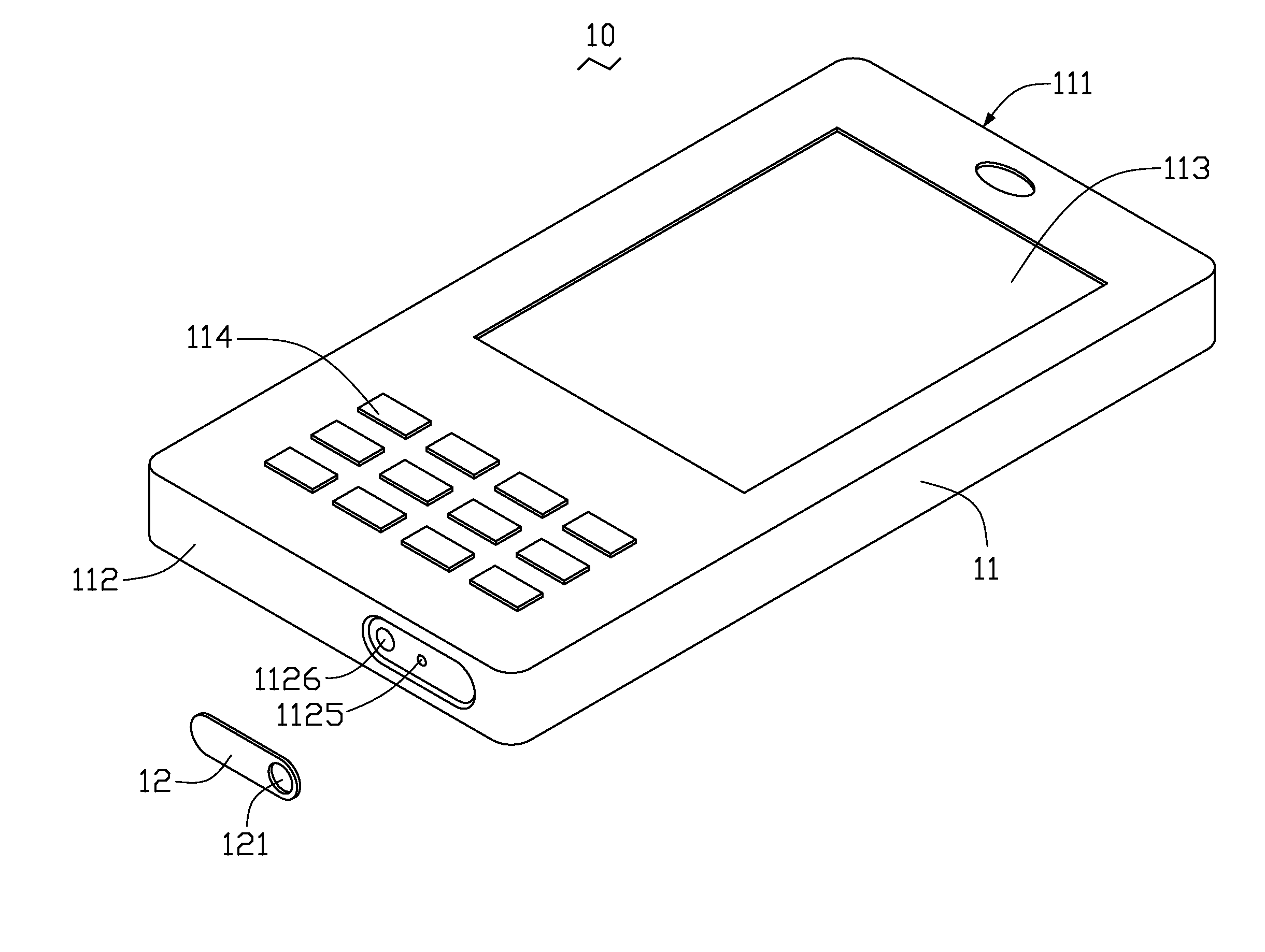
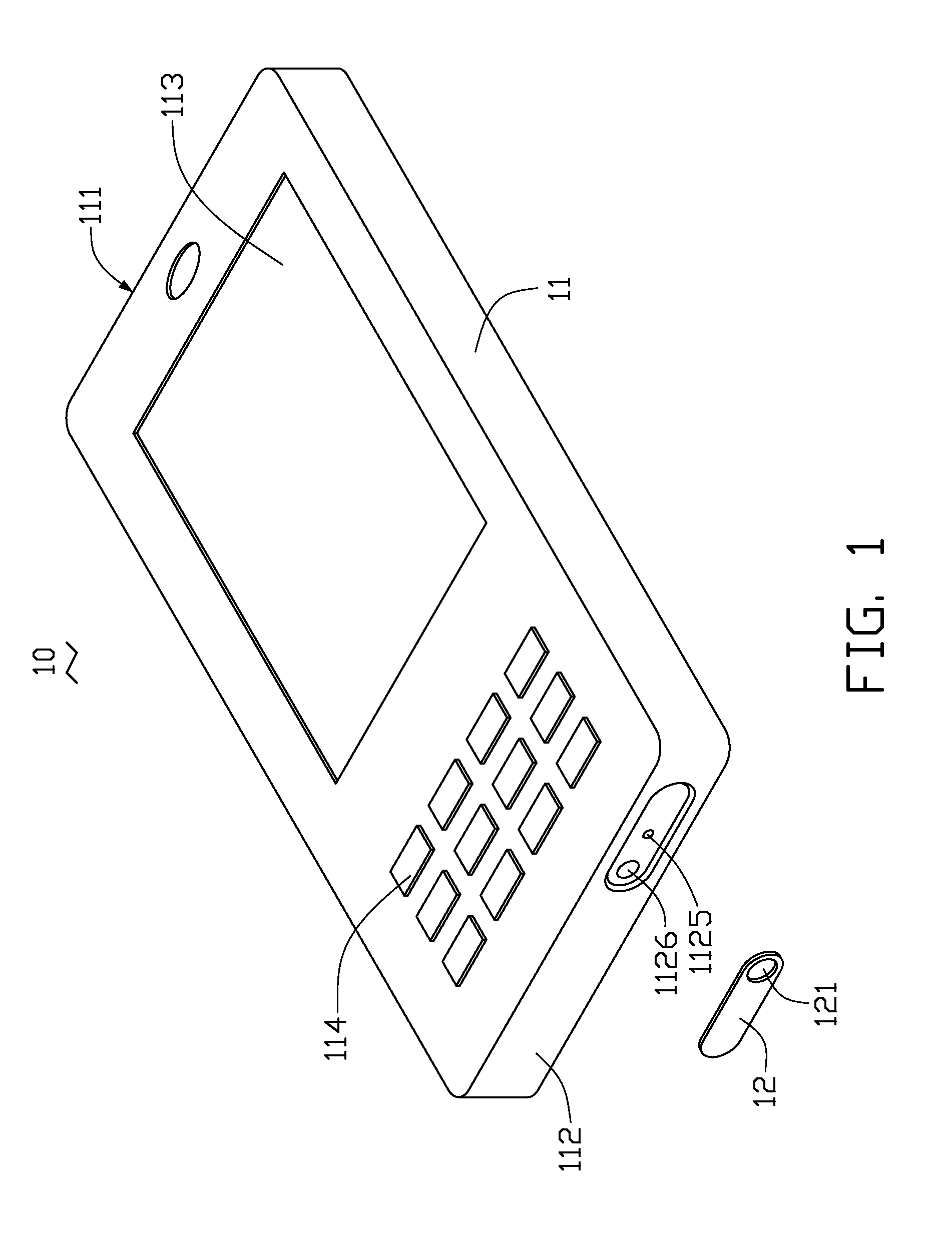
[0015]FIGS. 1 through 3 show an exemplary cover assembly 10 used in a portable electronic device such as a mobile phone. The cover assembly 10 includes a body member 11 and a cover member 12.

[0016]The body member 11 can be a housing of the portable electronic device. The body member 11 includes a top end 111 and an opposite bottom end 112. The body member 11 has a display 113 arranged adjacent to the top end 111 and a keypad 114 arranged adjacent to bottom end 112.

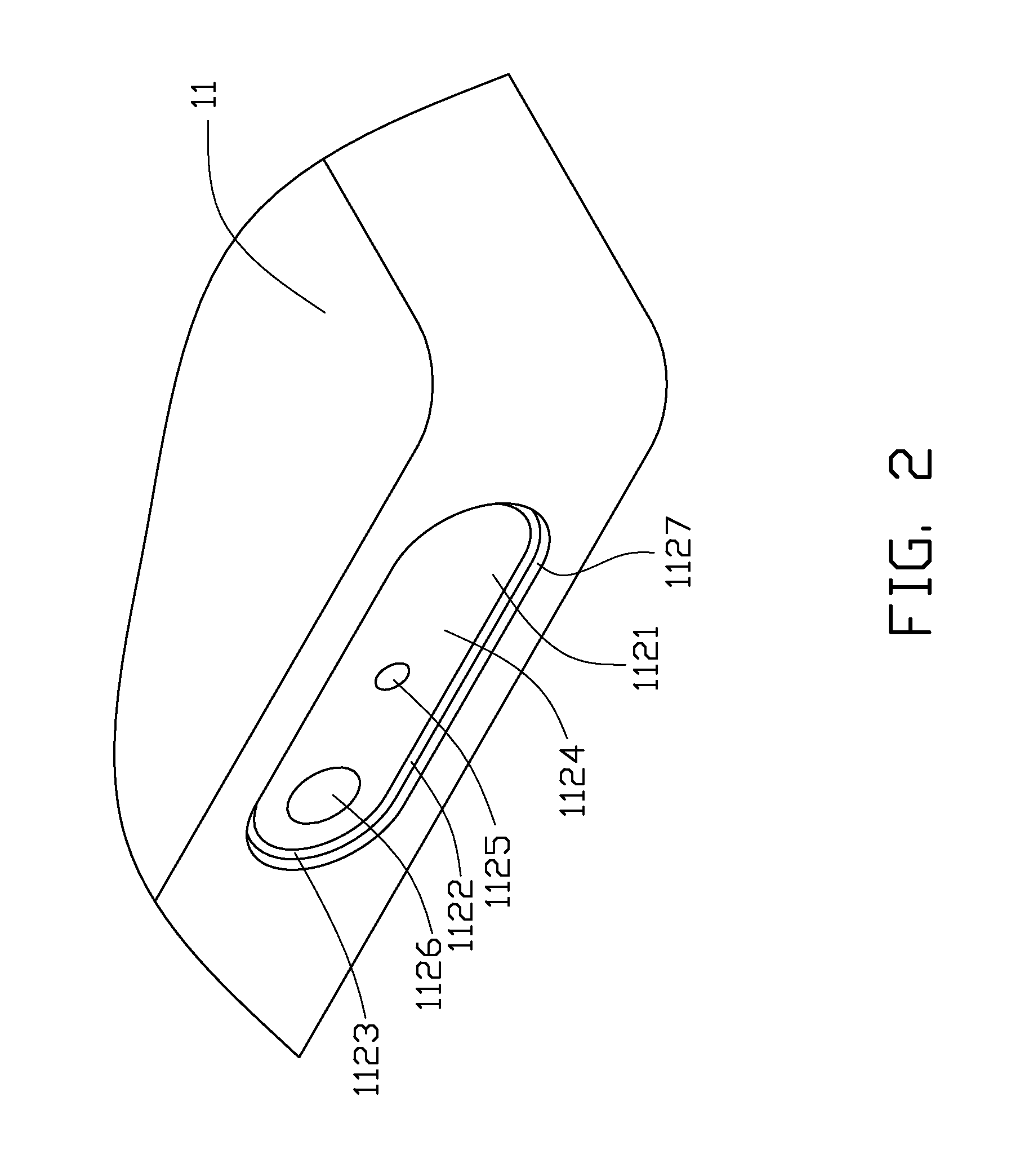
[0017]Referring also to FIG. 2, the bottom end 112 defines a cavity 1121, formed by two parallel planar walls 1122, two opposite curved walls 1123 and a bottom wall 1124. The bottom wall 1124 defines a round pivoting hole 1125 and a round jack 1126. The pivoting hole 1125 is located at a center of the bottom wall 1124. The jack 1126 is located at one end of the bottom wall 1124. The planar walls 1122 and the curved walls 1123 connect to the bottom end 112 via a plurality of guiding walls 1127. The guiding walls 1127 guide ...


PUM


Abstract

A cover assembly for a portable electronic device includes a body member defining a jack and a cover member defining a through hole at one end. The cover member pivots relative to the body member to cover or expose the jack.

Description

BACKGROUND[0001]1. Field of the Invention[0002]The present invention relates to device assembly and, particularly, to a cover assembly used in a portable electronic device.[0003]2. Description of Related Art[0004]Portable electronic devices (e.g., mobile phones) usually have earphone holes for insertion of earphones. Covers may be used to cover and protect the earphone holes from e.g., water and dust.[0005]A typical earphone cover is often made of rubber and is fixedly connected to the mobile phone by a flexible strip adjacent to the earphone hole. The covering / exposing of the earphone hole is achieved by bending the earphone cover towards / away from the earphone hole around the flexible strip.[0006]However, the flexible strip may not sustain continued use and can easily break.[0007]Therefore, there is room for improvement within the art.BRIEF DESCRIPTION OF THE DRAWINGS[0008]Many aspects of the cover assembly can be better understood with reference to the following drawings. These d...

Claims


Application Information

Patent Timeline
IPC IPC(8): H01R13/44
CPCH04M1/0283
Inventor KUO, LING-MEI
Owner CHI MEI COMM SYST INC
Why Eureka
Try Eureka