Rope Grip Slip-Knot Device

a technology of slip-knots and ropes, which is applied in the direction of snap-fasteners, rod connections, manufacturing tools, etc., can solve the problem of reducing the effective cross-section of the opening between the inserts, and achieve the effect of reducing the effective cross-section of the opening

Active Publication Date: 2010-03-11
STAFFORD MFG CORP
View PDF22 Cites 6 Cited by
  • Summary
  • Abstract
  • Description
  • Claims
  • Application Information

AI Technical Summary

Benefits of technology

[0017]The Female end cap and the Male end cap are connected by the retaining collar. The connection allows the Female end cap and the Male end cap to be turned. The rope is placed in or through the circular openings of the connected inserts. To allow the device to be moved along the rope the circular opening of the combined inserts in the Female end cap aligns with the circular opening of the combined insert in the Male end cap. When the device is at the location desired, the Female end cap and the Male end cap are turned in opposite directions. This reduces the effective cross-section of the opening between the inserts, thus pinching the rope and holding the device in place.

Problems solved by technology

This reduces the effective cross-section of the opening between the inserts, thus pinching the rope and holding the device in place.

Method used


Image

  • Rope Grip Slip-Knot Device
  • Rope Grip Slip-Knot Device
  • Rope Grip Slip-Knot Device

Examples


Embodiment Construction

[0033]There are a number of significant design features and improvements incorporated within the invention.

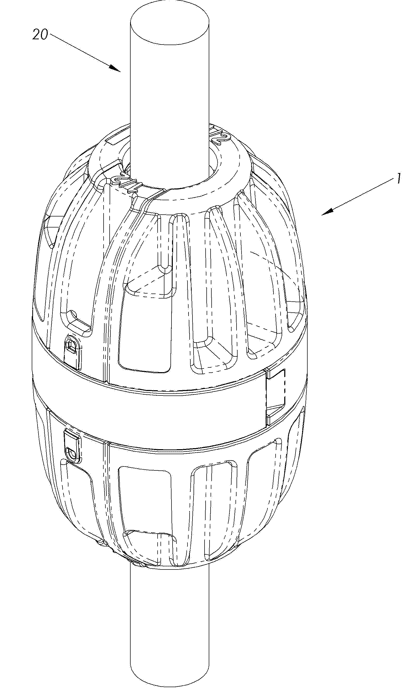
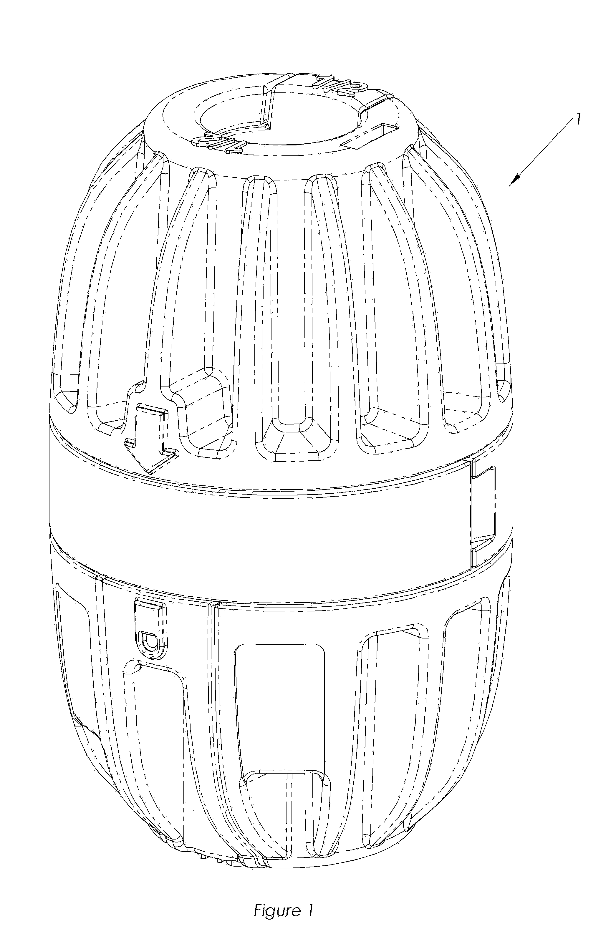
[0034]As shown in FIGS. 1 and 3, the present invention is a slip-knot grip device 1 which attaches to and secures to a rope 20. Properly sized Slip-Knot grip device 1 can be used to grip 2, 3 or more ropes, lines or cables, to form loops, bundles, etc.

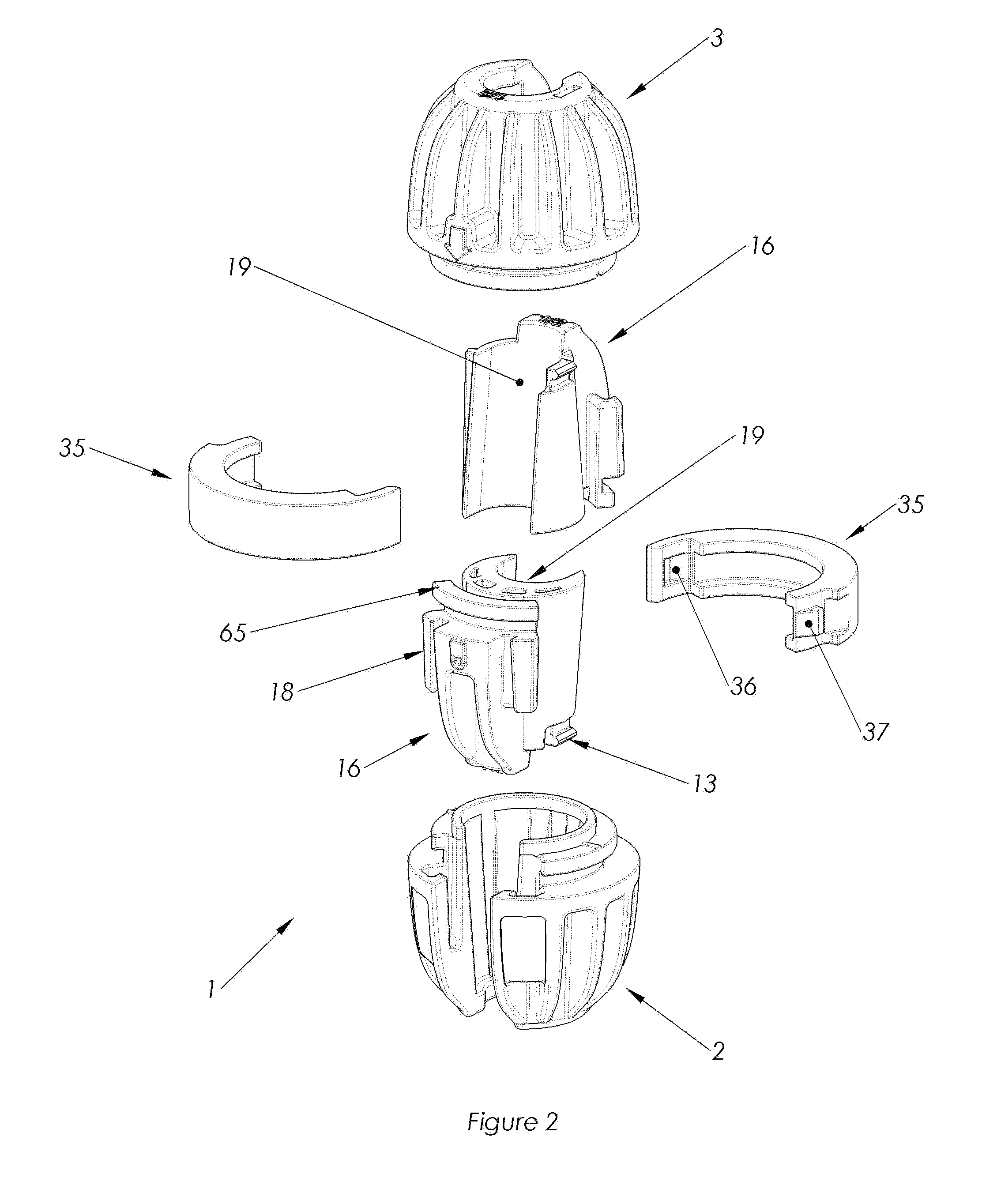
[0035]As shown in FIG. 2, the invention consists of a male end cap 2 into which an insert 19 is placed and a female end cap 3 into which another insert 19 is placed with the two end caps being connected by a retaining collar 35. The inserts are interchangeable. There is no difference between the top insert 19 and the bottom insert 19. FIG. 6 is a side view of the two end caps, Female and Male 12 connected by the retaining collar 35. In the preferred embodiment, there is a male end cap 2 and a female end cap 3.

[0036]The female end cap 3 and the male end cap 2 are connected by the retaining collar 35. The connection allows the femal...


PUM


Abstract

The present invention is a slip-knot grip device which attaches to a rope. The invention consists of a male end cap into which an insert is placed and a female end cap into which an insert is placed with the two end caps being connected by a retaining collar. The inserts have a semi-circle channel on their interior side placed so when the left and right inserts are connected together they form a circle opening through which a rope is placed. The female end cap and the male end cap are turned in opposite directions. This makes the end edges of the combined inserts clasp the rope holding the device in place.

Description

CROSS-REFERENCES TO RELATED APPLICATIONS (IF ANY)[0001]NoneSTATEMENT AS TO RIGHTS TO INVENTIONS MADE UNDER FEDERALLY-SPONSORED RESEARCH AND DEVELOPMENT (IF ANY)[0002]NoneBACKGROUND OF INVENTION[0003]1. Field of the Invention[0004]The present invention is directed to a rope grip device, more particular to one that is easy to use and attach to a rope to provide a method of providing an easily adjustable stop to limit the movement of rope as well as to locate and easily relocate associated items along a length of rope. As well as to provide a hand-grip to make rope tensioning easier, and to bundle two or more smaller ropes together.[0005]2. Background[0006]The use of ropes has been around for centuries. Sailors and sailing ships have used ropes to secure sails and cargo. There have been a number of types of knots that have been used with rope and methods to secure the rope and things to the rope.[0007]There still exists a need for the quick and easy method of securing a grip to functio...

Claims


Application Information

Patent Timeline
Patent Type & Authority Applications(United States)
IPC IPC(8): A44B21/00
CPCF16G11/00Y10T24/3922Y10T24/3969Y10T24/2158Y10T24/3996Y10T403/7054F16G11/048
Inventor STAFFORD, ARTHURTINSTMAN, MICHAEL DAVIDARMSTRONG, DANIEL RICHARDLITEPLO, WILLIAM PAULFIEGENER, JOHN DARIN
Owner STAFFORD MFG CORP
Why Eureka
Try Eureka