Configuration of air intake parts applied to thermal type air flow measuring instrument

a technology of air intake parts and measuring instruments, applied in the direction of instruments, machines/engines, electric control, etc., can solve the problems of dust being stuck to the heating resistor more easily, reducing the measuring accuracy, and the air flow measurement range is actually limited, so as to increase the flow rate and increase the flow rate of the air flowing. , the effect of increasing the flow velocity at the center of the main air passag

Inactive Publication Date: 2009-03-12
HITACHI LTD
View PDF12 Cites 3 Cited by
  • Summary
  • Abstract
  • Description
  • Claims
  • Application Information

AI Technical Summary

Benefits of technology

[0015]Feeding the air, which is different from the air flowing through the inlet of the main air passage, into the downstream of the squeezing configuration, allows the flow rate of the air flowing through the main air passage to increase while keeping the flow velocity at the center of the main air passage increased. The higher the flow rate at which the air flows through the squeezing configuration, that is, the higher the flow velocity at which the air flows through the squeezing configuration, the more air flows through this air introducing passage. This is because exfoliation occurs in the air flow downstream of the squeezing configuration and a pressure decreases, and the higher the flow rate at which the air flows through the squeezing configuration, the greater the pressure dr

Problems solved by technology

However, the air flow measuring range is actually limited when the measuring accuracy of the heating resistor and durability affected by stuck dust included in the air or the like are taken into consideration.
That is, since heat discharge of the heating resistor is extremely small at an imperceptible flow velocity, influences of natural convection due to heating and measuring errors due to individual variations of the heating resistor or the like relatively increase, resulting in a reduction of

Method used


Image

  • Configuration of air intake parts applied to thermal type air flow measuring instrument
  • Configuration of air intake parts applied to thermal type air flow measuring instrument
  • Configuration of air intake parts applied to thermal type air flow measuring instrument

Examples


embodiment 1

[0031]Operating principles of a thermal type air flow measuring instrument using a heating resistor will be explained as an example of an intake air measuring instrument. FIG. 8 is a schematic configuration circuit diagram of the thermal type air flow measuring instrument.

[0032]The drive circuit of the thermal type air flow measuring instrument is roughly divided into and constructed of a bridge circuit and a feedback circuit. The bridge circuit is constructed of a heating resistor RH for measuring an intake air flow, a temperature sensing resistor RC for compensating an intake air temperature and R10 and R11, and a heating current Ih is let flow through the heating resistor RH so as to keep a constant temperature difference between the heating resistor RH and the temperature sensing resistor RC while giving feedback using an operational amplifier OP1 and an output signal V2 in accordance with the air flow rate is outputted. That is, when the flow velocity is high, the amount of hea...

embodiment 2

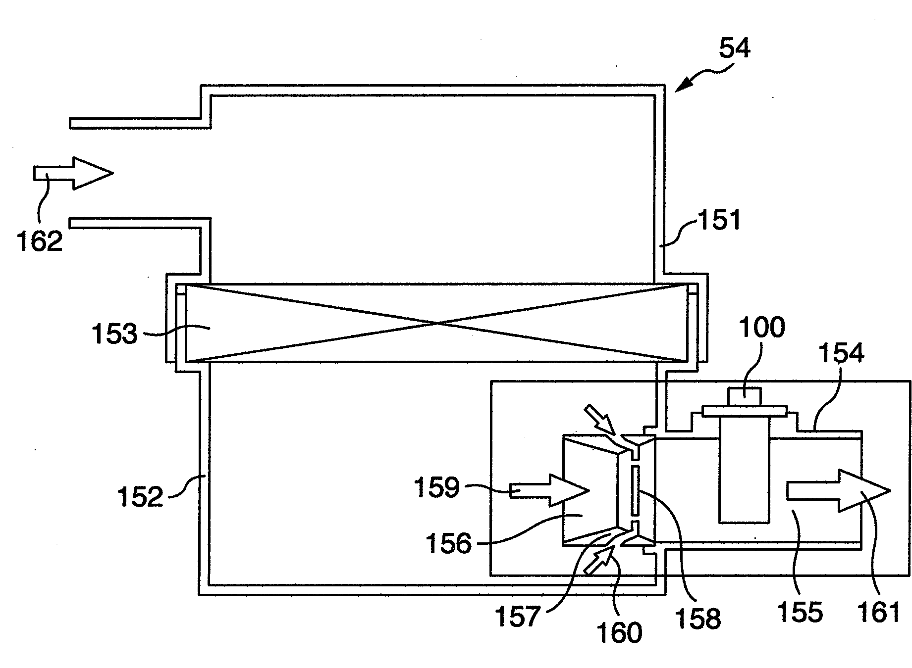
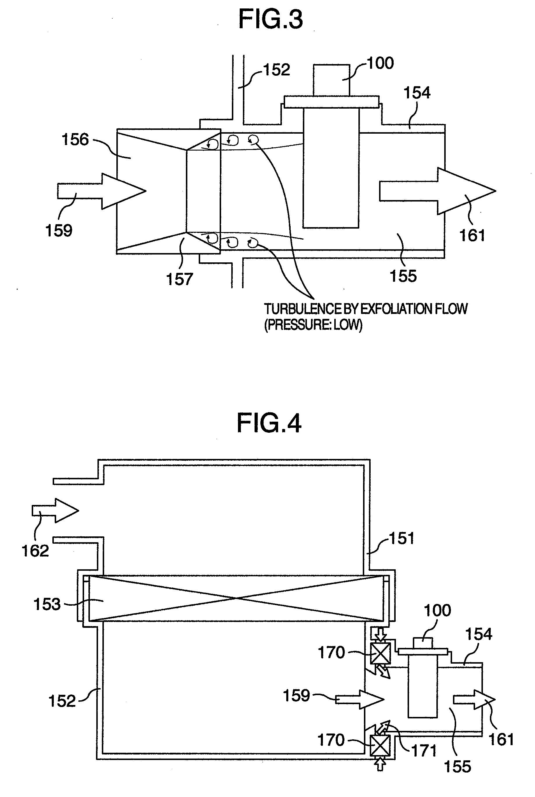
[0057]Next, another embodiment will be explained using FIG. 4 and FIG. 5. The basic configuration is the same as that in FIG. 1, but this embodiment does not use the duct that protrudes inside the clean side case 152 of the air cleaner used in FIG. 1. Instead, an air filter element 170 is used to clean the air flowing through the slit 173. Like Embodiment 1, the slit 173 forms an air passage that communicates the inside of the duct and the outside of the duct downstream of the main air passage inlet 174 without passing through the main air passage inlet 174 and the air flowing from the slit 173 into the downstream of the squeeze 172 is introduced into the main air passage without passing through the main air passage inlet 174.

[0058]This embodiment can also achieve the same effect as that in FIG. 1, but since this embodiment requires another filter, it is necessary to evaluate which of the two is selected by comparing the cost and effect with those in the case where a duct protruding...


PUM


Abstract

It is an object of the present invention to expand an air flow measuring range of a thermal type air flow measuring instrument. A squeeze 157 is provided upstream of a thermal type air flow measuring instrument 100 of a main air passage 155 to expand an air flow measuring range on the low flow rate side. Furthermore, a slit 158 is provided to introduce air from the outside of the main air passage 155 to a position downstream of the squeeze 157 where flow exfoliation occurs without passing thorough a main air passage inlet 156 to prevent a pressure drop from increasing at a high flow rate and expand the air flow measuring range on the high flow rate side.

Description

BACKGROUND OF THE INVENTION AND RELATED ART STATEMENT[0001]The present invention relates to air intake parts applied to a thermal type air flow measuring instrument suitable for use in an air intake flow rate measurement of an internal combustion engine.[0002]There is known a thermal type air flow measuring instrument as a flow rate measuring technique for an internal combustion engine. This instrument uses the fact that there is a correlation between an amount of heat deprived from a heating resistor and an inflow rate, can directly measure a mass flow rate necessary for engine combustion control, and is therefore widely used particularly as a flowmeter for air fuel ratio control of vehicles (see JP-A-11-14423).[0003]As a known technique most similar to the present invention, an example is shown where a squeeze is provided upstream of an auxiliary air passage of a thermal type air flow measuring instrument of an intake pipe component (see JP-A-10-73465).BRIEF SUMMARY OF THE INVENTI...

Claims


Application Information

Patent Timeline
IPC IPC(8): F02D41/18
CPCG01F5/00G01F1/6842
Inventor SHOYAMA, TAIJIASANO, YASUHIROKIKAWA, HIROMUKOBAYASHI, CHIHIRO
Owner HITACHI LTD
Why Eureka
Try Eureka