Disk player and worm mechanism for same

a technology of worm mechanism and disk player, which is applied in the field of disk player, can solve the problems that users sometimes encountered a trouble that the tray was not moved to the loading position, and achieve the effect of reducing the effective cross section and reducing the magnitud

Inactive Publication Date: 2007-08-14
FUNAI ELECTRIC CO LTD
View PDF15 Cites 0 Cited by
  • Summary
  • Abstract
  • Description
  • Claims
  • Application Information

AI Technical Summary

Benefits of technology

[0008]Accordingly, it is a first object of the present invention to provide a worm mechanism for a disk player, which worm mechanism ensures the translational movement of a tray for loading the disk without any self-lock of the motor, when the tray is pushed by a finger of a user.
[0009]Furthermore, it is a second object of the present invention to provide a disk player, which ensures the translational movement of a tray for loading the disk without any self-lock of the motor, when the tray is pushed by a finger of a user.
[0011]The structural arrangement of the worm mechanism in the first aspect of the invention provides a reduced effective cross section for the connection part of the worm gear, so that the partial force in the direction perpendicular to the axis of the worm gear resulting from the push of the tray causes the worm gear to be elastically deformed such that it is bent at the connection part. As a result, the partial force having the vertical component can be transmitted to the rotary shaft for the motor in a greatly reduced magnitude, thereby enabling the self-lock of the motor to be securely suppressed.
[0016]The structural arrangement of the disk player in the second aspect of the invention provides a reduced effective cross section for the connection part of the worm gear, so that the partial force in the direction perpendicular to the axis of the worm gear resulting from the push of the tray causes the worm gear to be elastically deformed such that it is bent at the connection part. As a result, the partial force having the vertical component can be transmitted to the rotary shaft for the motor in a greatly reduced magnitude, thereby enabling the self-lock of the motor to be securely suppressed. This ensures a smooth and continuous translational movement of the tray, when the tray is pushed by a finger to load the disk.
[0021]The structural arrangement of the disk player in the third aspect of the invention provides a reduced effective cross section for the connection part of the worm gear, so that the partial force in the direction perpendicular to the axis of the worm gear resulting from the push of the tray causes the worm gear to be elastically deformed such that it is bent at the connection part. As a result, the partial force having the vertical component can be transmitted to the rotary shaft for the motor in a greatly reduced magnitude, thereby enabling the self-lock of the motor to be securely suppressed. This ensures a smooth and continuous translational movement of the tray, when the tray is pushed by a finger to load the disk.

Problems solved by technology

In such a conventional disk player, users sometimes encountered a trouble that the tray was not moved any longer to the loading position, even when the tray was pushed by their finger.

Method used


Image

  • Disk player and worm mechanism for same
  • Disk player and worm mechanism for same
  • Disk player and worm mechanism for same

Examples


first embodiment

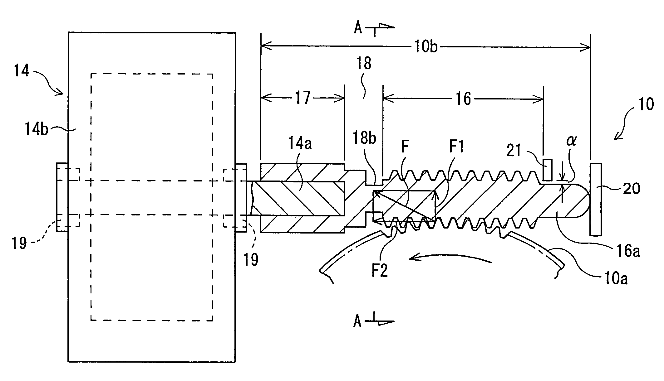
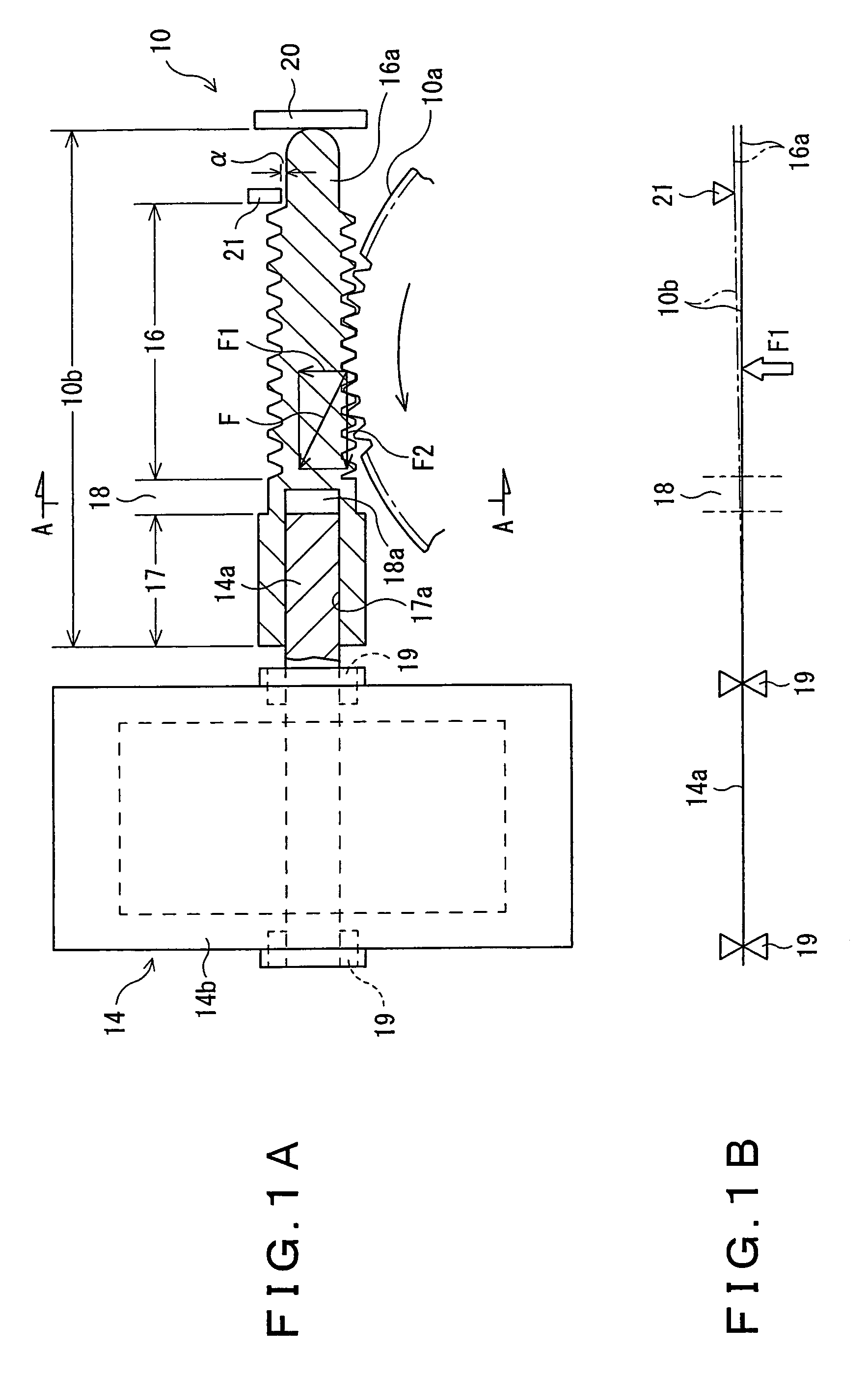
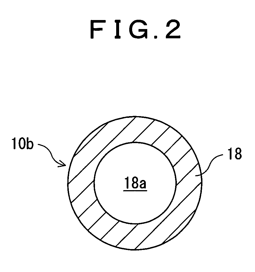
[0047]FIGS. 1A, 1B and 2 illustrate the structural arrangement of a substantial section in a disk player of a first embodiment according to the invention. A connection part 18 of a worm gear 10b is formed such that it has the same diameter as a screw shaft part 16. In this case, a boss part 17 is formed such that it has a coaxial hollow cylindrical hole 18a having the same diameter as that of a hole 17a into which a driving shaft 14a of a feed motor 14 is inserted (referred to as a driving shaft-inserting hole). Accordingly, the effective cross section of the connecting part 18 is smaller than that of the screw shaft part 16. The arrangement of structural elements other than the above-mentioned ones is substantially the same as that shown in FIGS. 5-8, so that similar symbols are allocated to corresponding parts and the description of the function thereof will be omitted.

[0048]In the above arrangement, when the tray 1 in the farthest advanced state (a) is pushed by finger H, a pushi...

second embodiment

[0051]FIGS. 3A, 3B and 4 illustrate the structural arrangement of a substantial section in a disk player of a second embodiment according to the invention. In this case, an annular groove 18b is formed on the outer surface of a connection part 18 in a worm gear 10b, and the effective cross section of the connection part 18 is determined to be smaller than that of a screw shaft part 16. The arrangement of structural elements other than the above-mentioned ones is substantially the same as that shown in FIGS. 1A, 1B and 2, so that similar symbols are allocated to corresponding parts and the description of the function thereof will be omitted.

[0052]In this structural arrangement of the second embodiment, a similar effect to that in the disk player of the first embodiment can be obtained. It is noted that the worm gear 10b having a smaller effective cross section than that of the screw shaft part 16 can easily be realized only by forming such an annular groove 18b on the outer surface o...


PUM

PropertyMeasurementUnit
pushing forceaaaaaaaaaa
forceaaaaaaaaaa
vertical forceaaaaaaaaaa

Abstract

A worm mechanism for a disk player includes a worm gear securely connected to a rotary shaft of a motor, a worm wheel coupled to the worm gear and further connected to driving mechanisms in the disk player and a radial stopper, wherein the worm gear including a boss part securely connected to said rotary shaft, a screw shaft part and a connection part coaxially formed between the boss part and screw shaft part in a unified structure, wherein the radial stopper is disposed on the other side of the worm wheel, apart from the screw shaft part in a predetermined gap in the vicinity of the end of the screw shaft part opposite to the boss part and wherein the connection part has in at least part thereof in the axial direction an effective cross section which is smaller than the cross section of the screw shaft part.

Description

BACKGROUND OF THE INVENTION[0001]1. Field of the Invention[0002]The present invention relates to a disk player, which is used for reproducing, recording or eliminating data on an optical disk, such as DVD-RW, or a magnetic disk (hereinafter referred to as a disk), and it also relates to a worm mechanism for such a disk player. More specifically, the present invention relates to an improvement of a disk player and a worm mechanism for the same, where such a disk is loaded into the disk player by applying a pushing force to a tray for the disk.[0003]2. Description of the Related Art[0004]Such a disk player is equipped with a loading mechanism, which permits loading a disk thereinto in order to reproduce data from the disk or to record data in the disk as well as to discharge the loaded disk therefrom. The loading mechanism includes three different driving mechanisms; a first driving mechanism is used to move a tray on which the disk is placed in the forward or backward direction (disc...

Claims


Application Information

Patent Timeline
Patent Type & Authority Patents(United States)
IPC IPC(8): G11B17/04G11B33/12F16H1/16
CPCG11B17/04
Inventor KURITA, TAKESHI
Owner FUNAI ELECTRIC CO LTD
Why Eureka
Try Eureka