

Aerosol Sprayer
a sprayer and actuator technology, applied in the field of pressurized sprayers and pressurized sprayer actuators, can solve the problems of finger fatigue in some users, less than adequate grip, and the inability to accurately direct the discharged product to the desired surface area
- Summary
- Abstract
- Description
- Claims
- Application Information
AI Technical Summary
Problems solved by technology
Method used
Image

Examples
Embodiment Construction
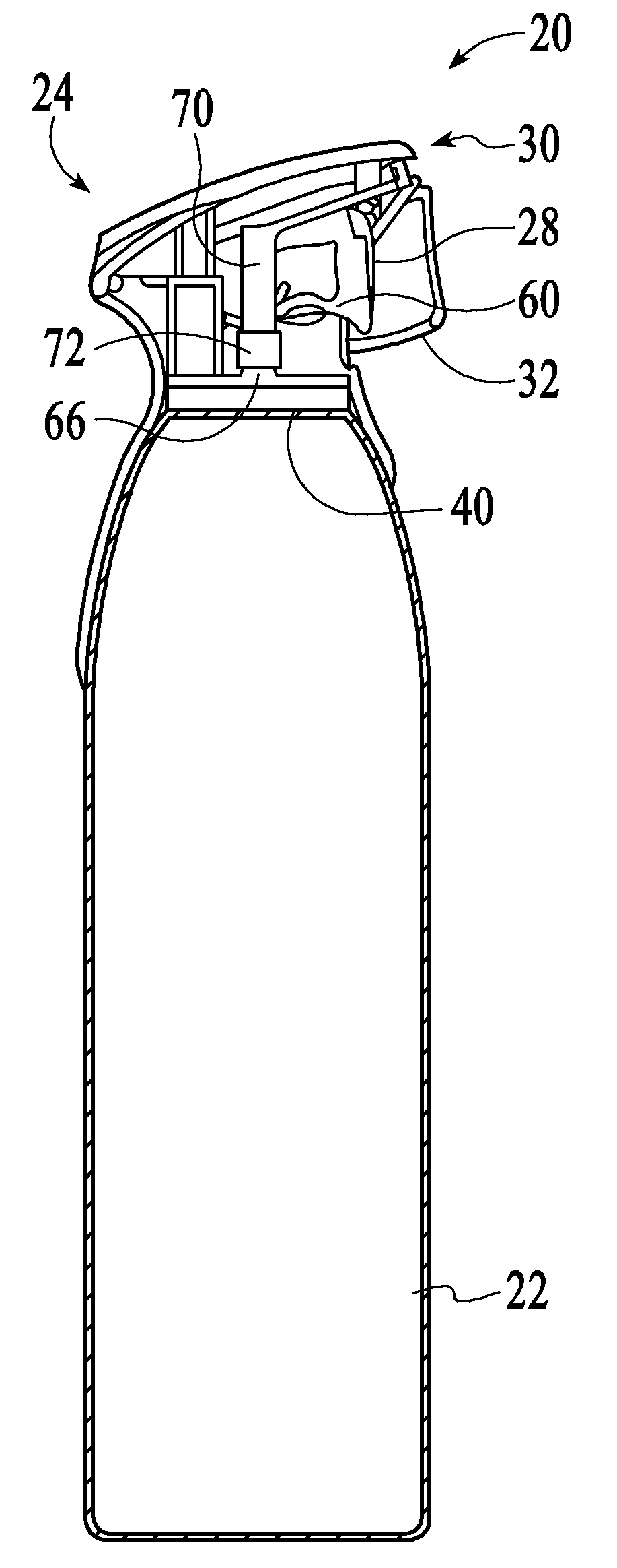
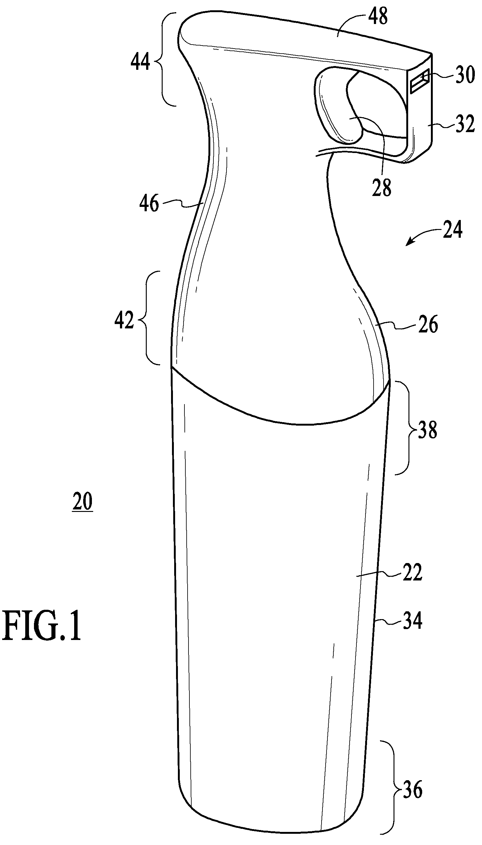
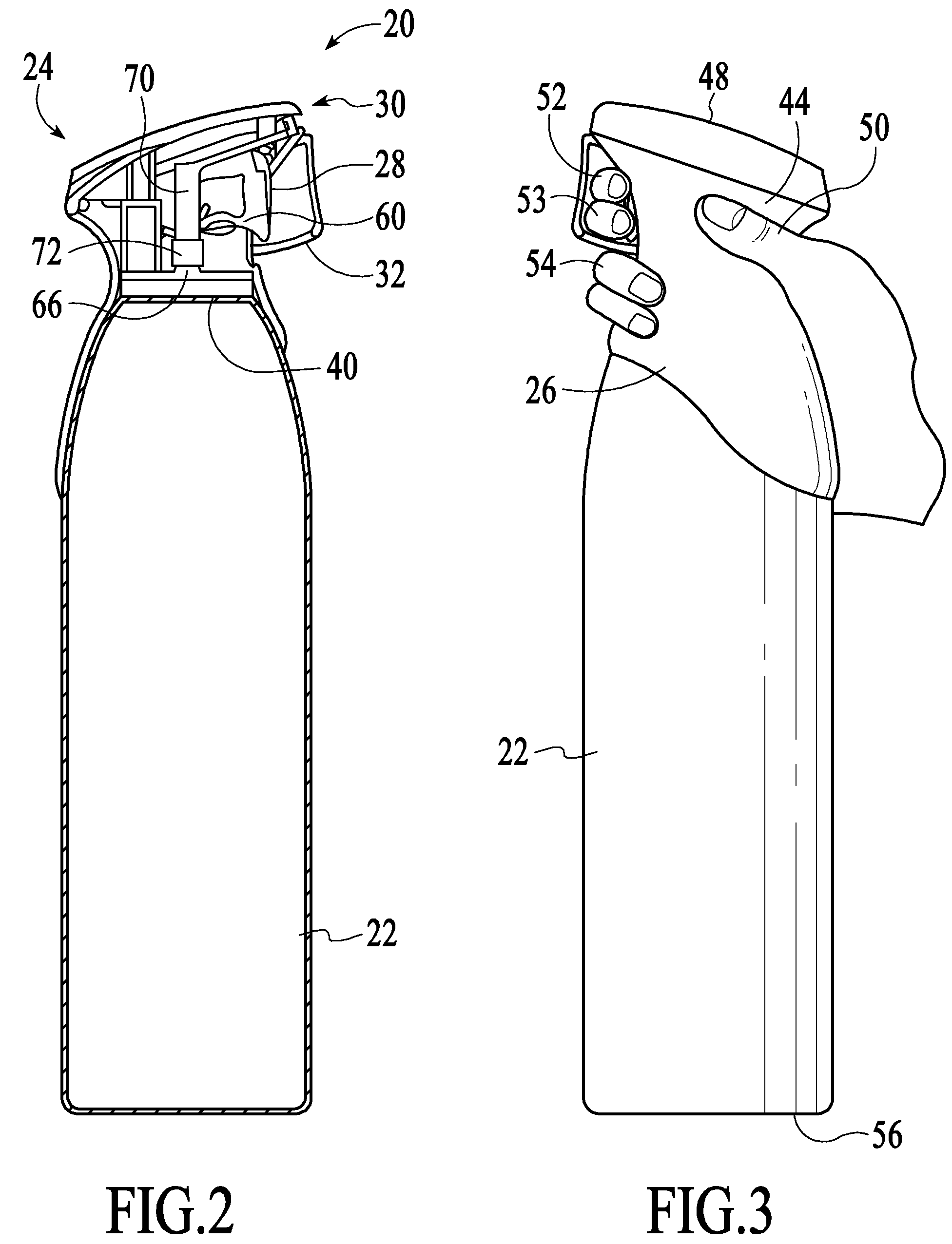
[0035]The present invention relates to a pressurized aerosol sprayer, a pressurized sprayer actuator, and a method of making the same. FIG. 1 shows one non-limiting embodiment of a pressurized sprayer 20. As shown in FIG. 1, the sprayer (or “spray container”) 20 comprises a container 22 and a sprayer actuator (or “actuator”) 24. The sprayer actuator 24 comprises a housing 26, a trigger 28, a nozzle 30, and a trigger loop 32.
[0036]The container 22 can be any suitable type of container for holding a product to be dispensed by the sprayer. In some embodiments, it is desirable for the container 22 to be capable of holding contents that are under pressure and / or a propellant. The design of such containers in the form of metal cans or plastic containers is well known. The container 22 can be of any suitable shape. The container 22 has sides 34, a lower portion 36, an upper portion 38, and a top 40 (shown in FIG. 2). In the embodiment shown, the container 22 is generally cylindrical, but t...
PUM
 Abstract
Description
Claims
Application Information